Cirkit Designer LogoCirkit DesignerYour all-in-one circuit design IDE Launch Cirkit Designer App

How to Use SPS30: Examples, Pinouts, and Specs

Image of SPS30Design with SPS30 in Cirkit Designer

Introduction

The SPS30 is a laser-based particulate matter (PM) sensor developed by Sensirion. It is designed to measure the concentration of airborne particles in various size ranges, including PM1, PM2.5, PM4, and PM10. The sensor utilizes advanced laser scattering technology and Sensirion's proprietary algorithms to deliver highly accurate and reliable real-time data. Its compact design, low power consumption, and long-term stability make it ideal for air quality monitoring applications.

Explore Projects Built with SPS30

Use Cirkit Designer to design, explore, and prototype these projects online. Some projects support real-time simulation. Click "Open Project" to start designing instantly!
Image of Multi-Sensor Environmental Monitoring System with Dual-Display Output: A project utilizing SPS30 in a practical application
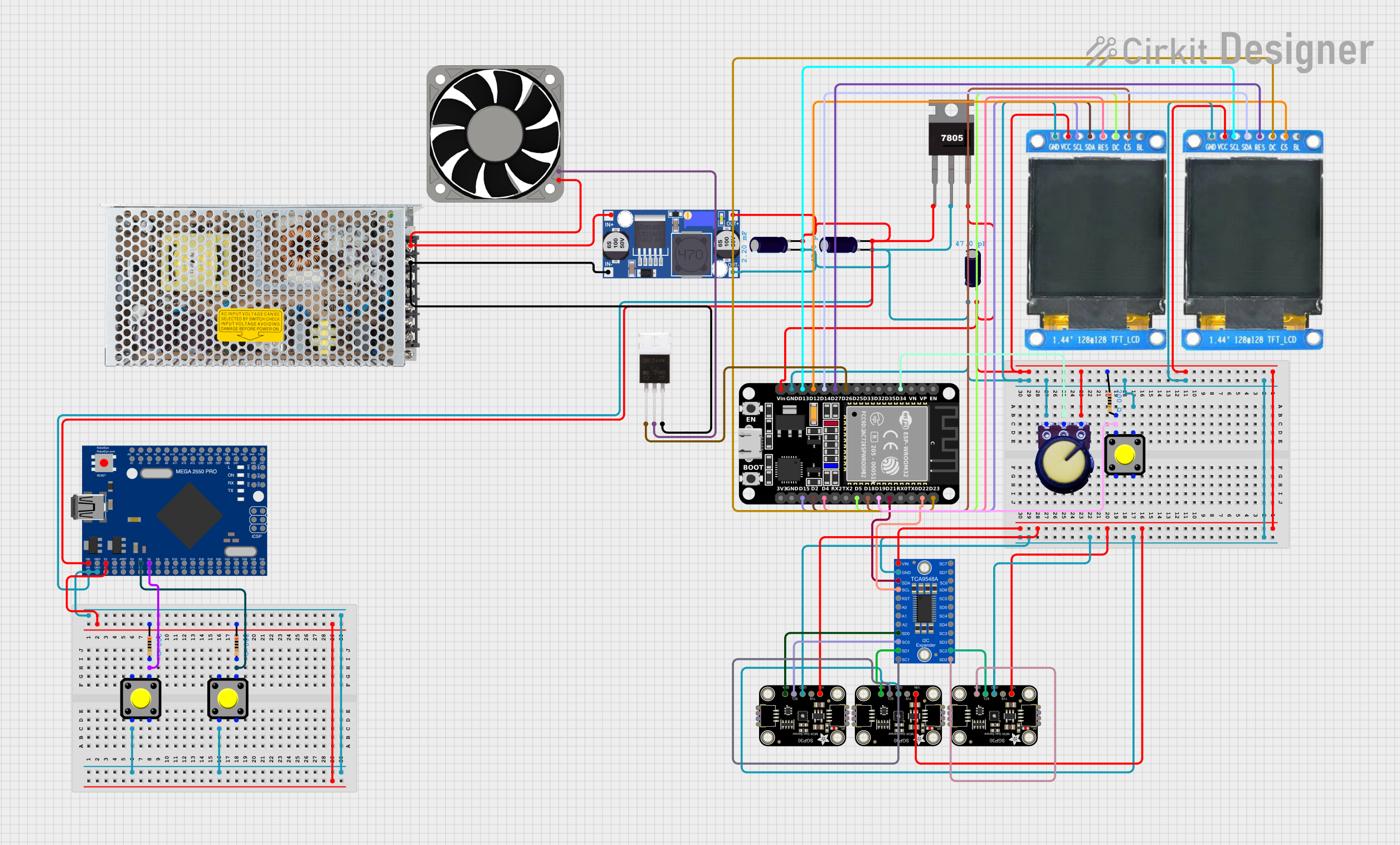
Multi-Sensor Environmental Monitoring System with Dual-Display Output

This circuit is designed for environmental monitoring and control, featuring multiple air quality sensors, visual output on TFT displays, and user interaction through pushbuttons and a potentiometer. It is controlled by an ESP32 microcontroller, which manages sensor data via an I2C multiplexer and controls a 12V fan through a MOSFET, suggesting applications in air quality assessment and automated ventilation systems.

Open Project in Cirkit Designer
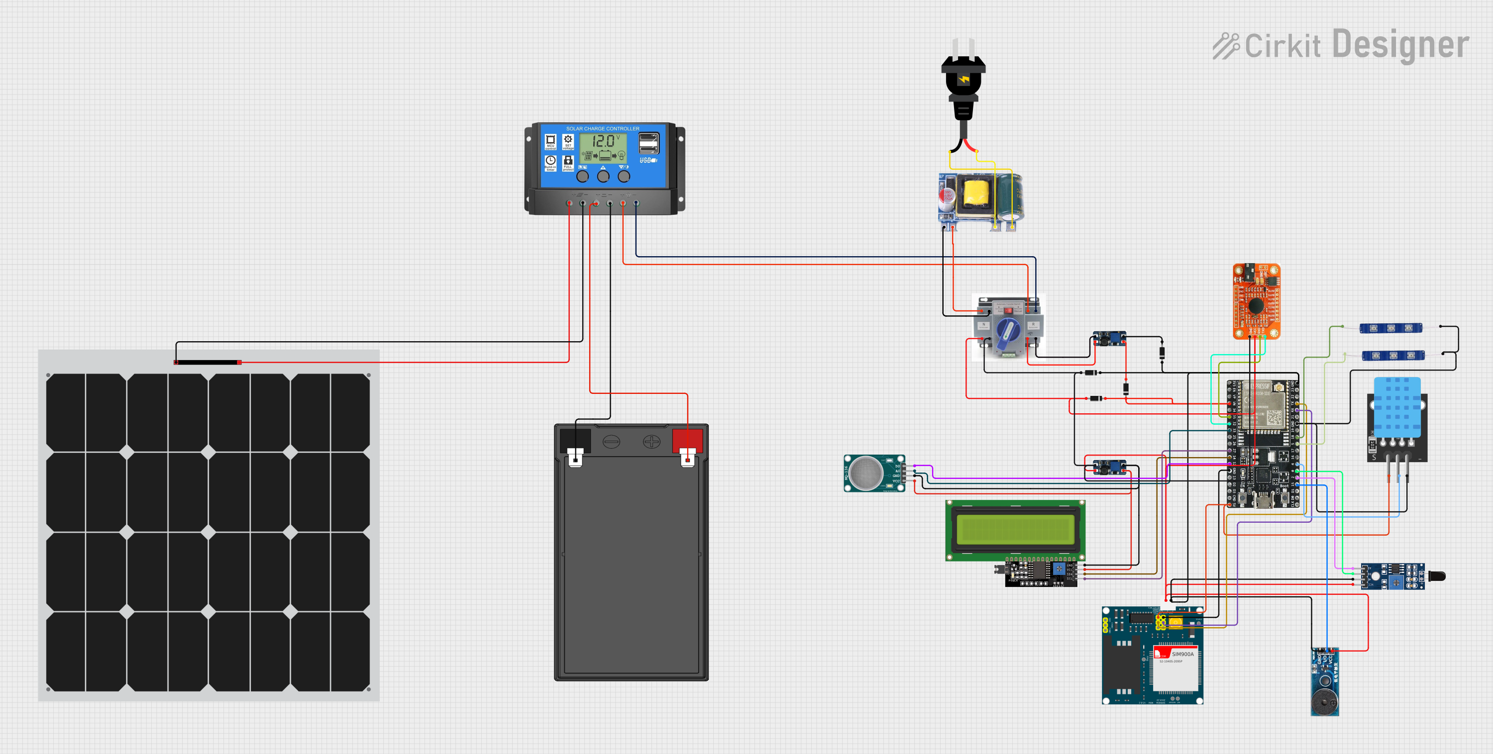
Image of Solar-Powered Environmental Monitoring Station with GSM Reporting: A project utilizing SPS30 in a practical application
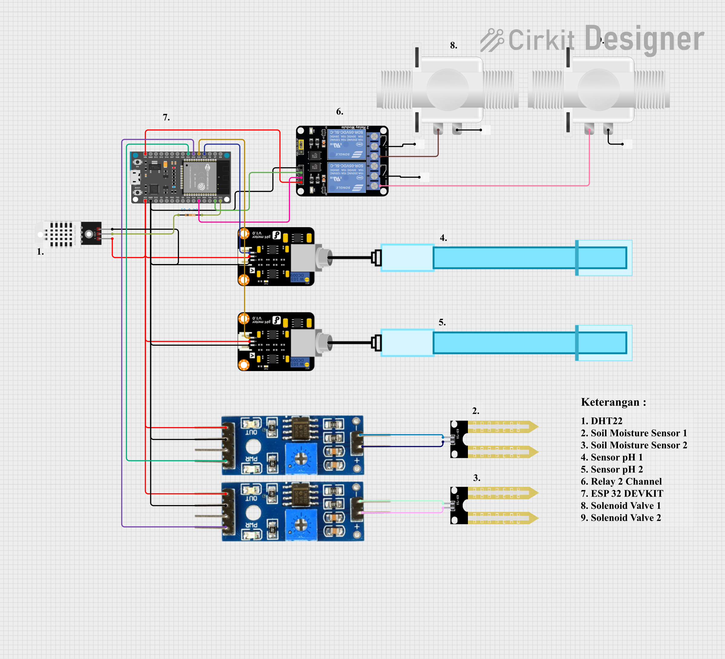
Solar-Powered Environmental Monitoring Station with GSM Reporting

This is a solar-powered monitoring and control system with automatic power source selection, environmental sensing, and communication capabilities. It uses an ESP32 microcontroller to process inputs from gas, flame, and temperature sensors, and to manage outputs like an LCD display, LEDs, and a buzzer. The system can communicate via a SIM900A module and switch between solar and AC power sources using an ATS.

Open Project in Cirkit Designer
Image of ESP32-S3 Based Vibration Detection System with TFT Display and Power Backup: A project utilizing SPS30 in a practical application
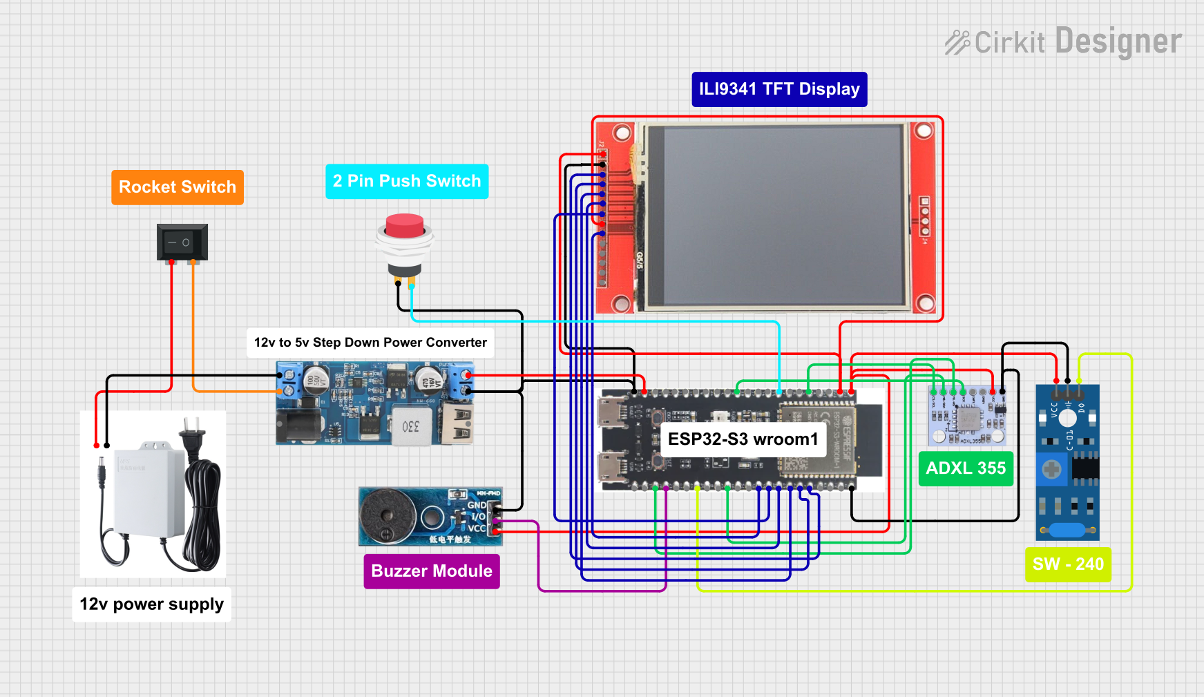
ESP32-S3 Based Vibration Detection System with TFT Display and Power Backup

This circuit features an ESP32-S3 microcontroller connected to various peripherals including an ADXL355 accelerometer, an SW-420 vibration sensor, a buzzer module, and an ILI9341 TFT display. The ESP32-S3 manages sensor inputs and provides output to the display and buzzer. Power management is handled by a 12V to 5V step-down converter, and a UPS ensures uninterrupted power supply, with a rocker switch to control the power flow.

Open Project in Cirkit Designer
Common Applications and Use Cases

Technical Specifications

The SPS30 is a high-performance sensor with the following key technical details:

Parameter Value
Measurement Principle Laser scattering
Particle Size Ranges PM1.0, PM2.5, PM4.0, PM10
Measurement Range 0–1,000 µg/m³
Accuracy ±10 µg/m³ (0–100 µg/m³)
Response Time < 8 seconds
Operating Voltage 5 V DC
Current Consumption < 60 mA
Communication Interfaces UART, I²C
Operating Temperature Range -10°C to +60°C
Operating Humidity Range 0–95% RH (non-condensing)
Dimensions 41 x 41 x 12 mm
Lifetime > 8 years (continuous operation)

Pin Configuration and Descriptions

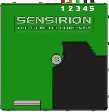
The SPS30 has a 7-pin connector for power and communication. The pinout is as follows:

Pin Number Name Description
1 VDD Power supply (5 V DC)
2 GND Ground
3 TX UART Transmit (data output)
4 RX UART Receive (data input)
5 SCL I²C Clock
6 SDA I²C Data
7 SEL Interface selection (GND for UART, VDD for I²C)

Usage Instructions

How to Use the SPS30 in a Circuit

  1. Power Supply: Connect the VDD pin to a 5 V DC power source and the GND pin to ground.
  2. Interface Selection: Use the SEL pin to select the communication interface:
    • Connect SEL to GND for UART communication.
    • Connect SEL to VDD for I²C communication.
  3. Communication:
    • For UART: Connect the TX pin to the RX pin of your microcontroller and the RX pin to the TX pin of your microcontroller.
    • For I²C: Connect the SCL and SDA pins to the corresponding I²C pins on your microcontroller.
  4. Pull-Up Resistors: If using I²C, ensure that pull-up resistors (typically 4.7 kΩ) are connected to the SCL and SDA lines.

Important Considerations and Best Practices

Example Code for Arduino UNO (I²C Communication)

Below is an example of how to interface the SPS30 with an Arduino UNO using I²C:

#include <Wire.h>
#include <SensirionI2CScd4x.h> // Include Sensirion library for SPS30

#define SPS30_I2C_ADDRESS 0x69 // Default I²C address for SPS30

void setup() {
  Wire.begin(); // Initialize I²C communication
  Serial.begin(9600); // Initialize serial communication for debugging

  // Initialize SPS30
  if (!sps30.begin(Wire)) {
    Serial.println("SPS30 initialization failed!");
    while (1); // Halt if initialization fails
  }
  Serial.println("SPS30 initialized successfully.");
}

void loop() {
  float pm2_5, pm10;

  // Read PM2.5 and PM10 concentrations
  if (sps30.readMeasurement(pm2_5, pm10)) {
    Serial.print("PM2.5: ");
    Serial.print(pm2_5);
    Serial.print(" µg/m³, PM10: ");
    Serial.print(pm10);
    Serial.println(" µg/m³");
  } else {
    Serial.println("Failed to read data from SPS30.");
  }

  delay(1000); // Wait 1 second before the next reading
}

Troubleshooting and FAQs

Common Issues and Solutions

  1. No Data Output:

    • Ensure the SEL pin is correctly configured for the selected communication interface.
    • Verify the wiring connections, especially the power and communication lines.
    • Check that the microcontroller's I²C or UART pins are correctly configured.
  2. Inaccurate Readings:

    • Ensure the sensor is placed in a location with good airflow and away from obstructions.
    • Verify that the power supply is stable and within the specified voltage range.
    • Allow the sensor to warm up for at least 10 seconds after powering on.
  3. Communication Errors:

    • For I²C, ensure pull-up resistors are connected to the SCL and SDA lines.
    • Verify the I²C address (default is 0x69) and update your code if necessary.
    • For UART, ensure the baud rate matches the sensor's default setting (typically 115200 bps).

FAQs

Q: Can the SPS30 measure particles smaller than PM1?
A: No, the SPS30 is designed to measure particles in the PM1, PM2.5, PM4, and PM10 size ranges.

Q: How often should the sensor be calibrated?
A: The SPS30 is factory-calibrated and does not require additional calibration during its lifetime.

Q: Can the SPS30 be used outdoors?
A: Yes, but it should be protected from direct exposure to water, dust, and extreme environmental conditions.

Q: What is the lifetime of the SPS30?
A: The sensor has a lifetime of over 8 years under continuous operation.