Cirkit Designer Logo
Cirkit Designer
Your all-in-one circuit design IDE
Home / 
Component Documentation

How to Use Raspberry Pi 3B: Examples, Pinouts, and Specs
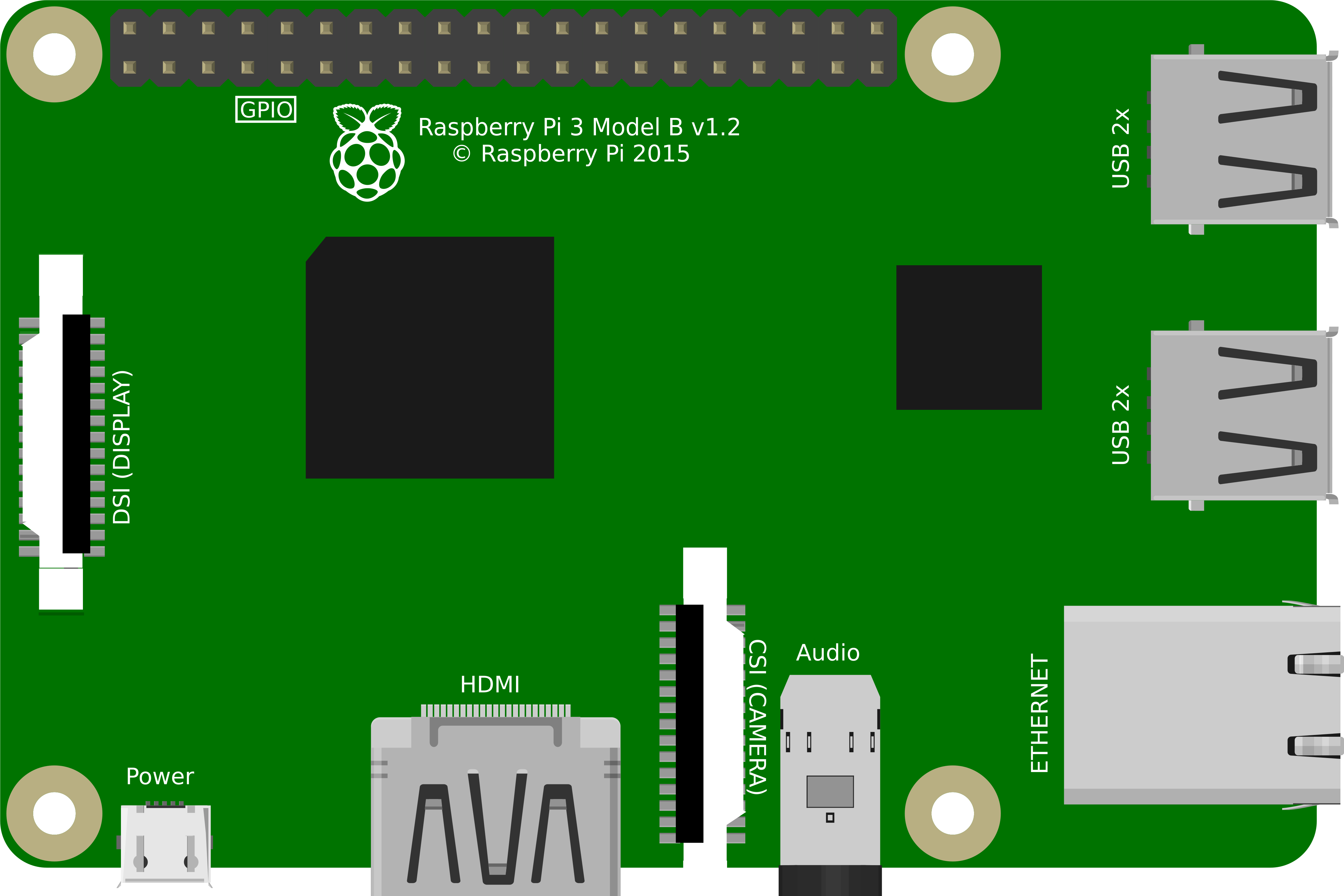

Image of Raspberry Pi 3B
Cirkit Designer LogoDesign with Raspberry Pi 3B in Cirkit Designer

Introduction

The Raspberry Pi 3B is a small, affordable single-board computer designed for a wide range of applications. It features a quad-core ARM Cortex-A53 processor, 1GB of RAM, and built-in Wi-Fi and Bluetooth connectivity. With its compact size and versatile GPIO pins, the Raspberry Pi 3B is ideal for projects such as programming, robotics, IoT devices, media centers, and more. Its affordability and ease of use make it a popular choice for both beginners and experienced developers.

Common applications include:

  • DIY home automation systems
  • Media streaming devices
  • Educational programming platforms
  • Robotics and hardware prototyping
  • IoT (Internet of Things) projects

Explore Projects Built with Raspberry Pi 3B
Use Cirkit Designer to design, explore, and prototype these projects online. Some projects support real-time simulation. Click "Open Project" to start designing instantly!
Raspberry Pi 3B-Based Smart Robot with Sensor Integration
Image of Float Robot: A project utilizing Raspberry Pi 3B in a practical application
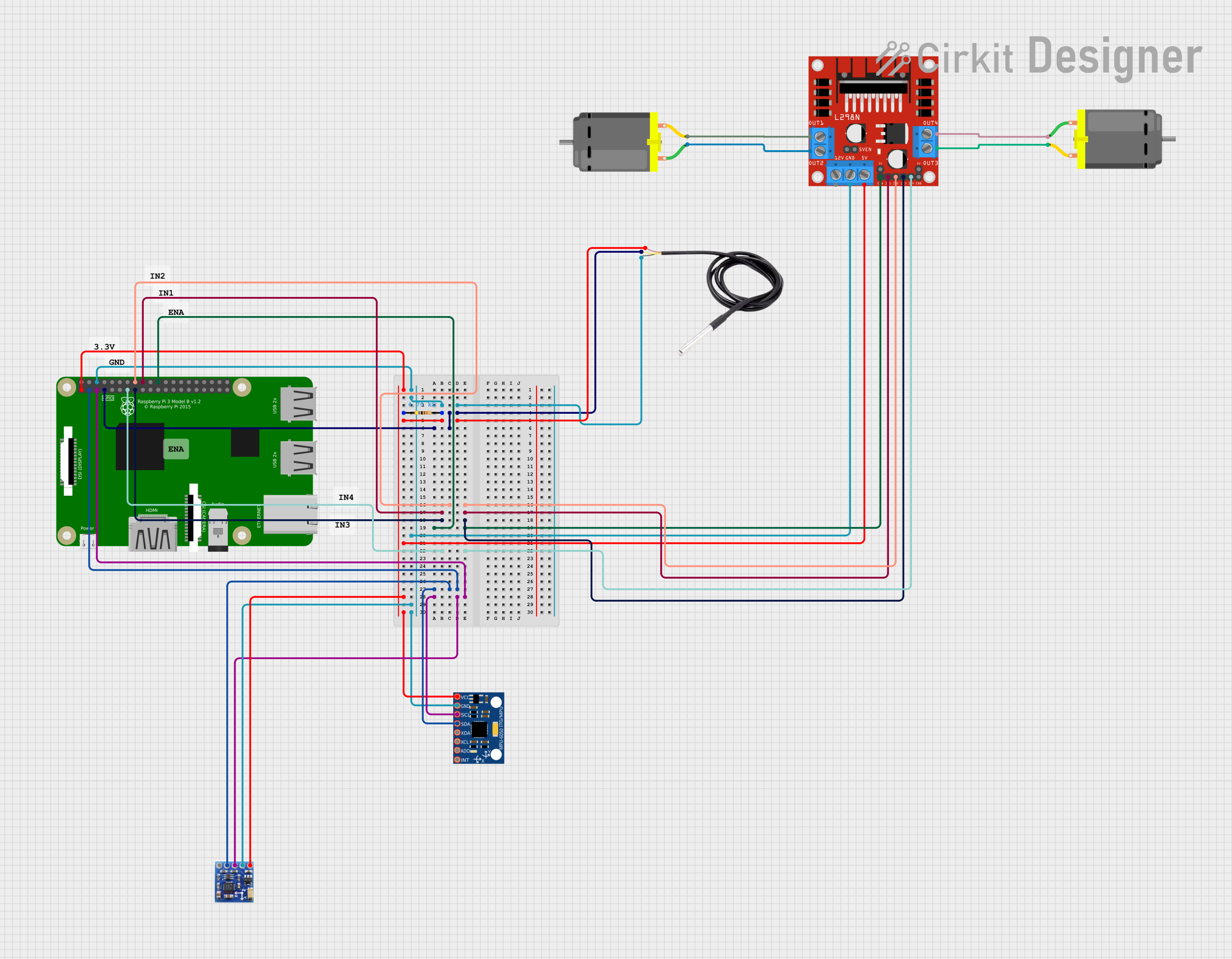
This circuit integrates a Raspberry Pi 3B with various sensors and a motor driver to create a multi-functional system. It includes a DS18B20 temperature sensor, MPU-6050 accelerometer and gyroscope, QMC5883L magnetometer, and an L298N motor driver controlling two DC motors. The Raspberry Pi handles sensor data and motor control through its GPIO pins.
Cirkit Designer LogoOpen Project in Cirkit Designer
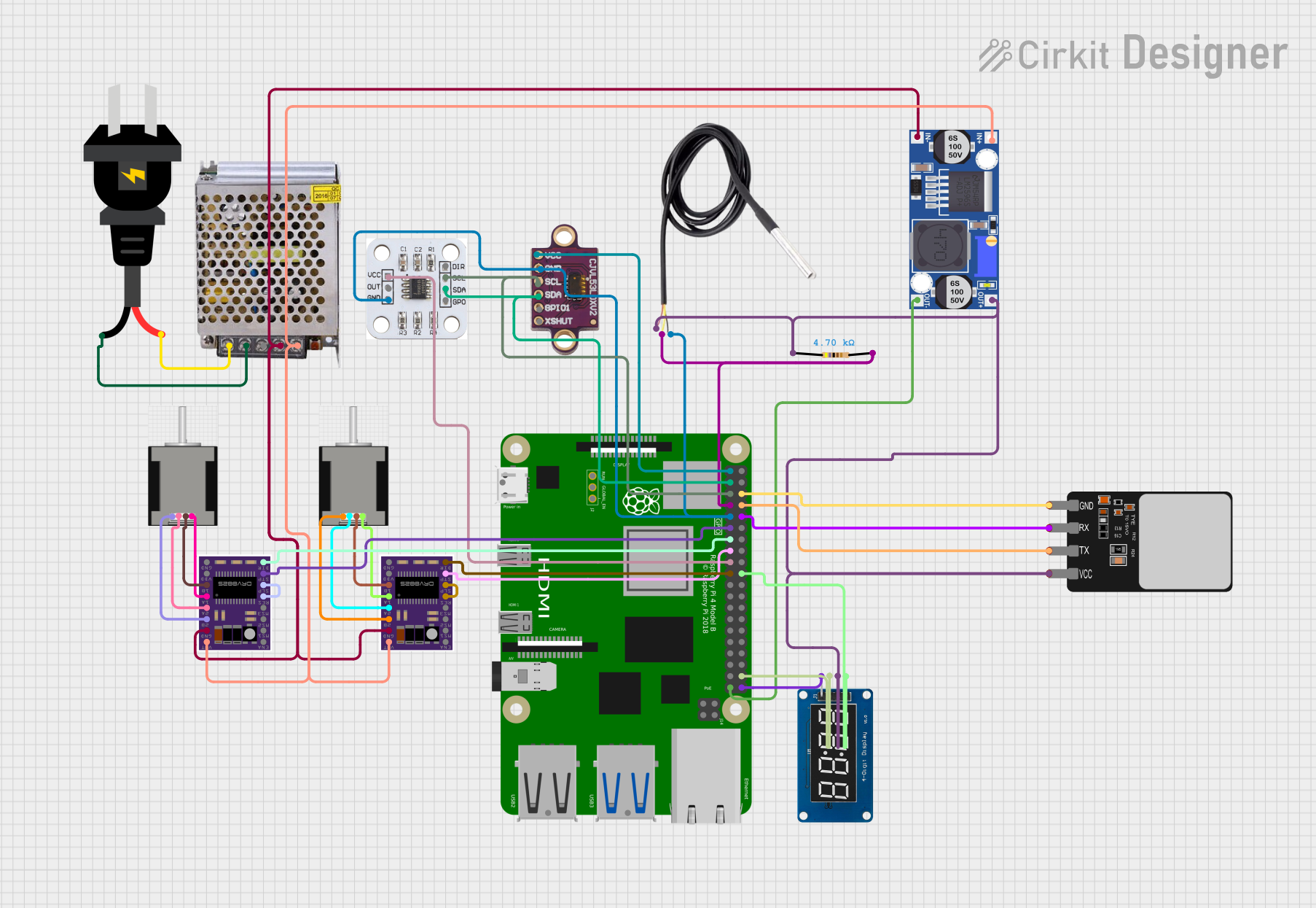
Raspberry Pi 4B-Controlled Biometric Access System with Dual Stepper Motor Actuation
Image of wiring: A project utilizing Raspberry Pi 3B in a practical application
This circuit features a Raspberry Pi 4B as the central controller, interfacing with various sensors and modules. It includes a vl53l0xv2 time-of-flight sensor and an AS5600 magnetic encoder for position sensing, both connected via I2C (SDA/SCL lines). The circuit also controls two DRV8825 stepper motor drivers connected to NEMA 17 stepper motors, receives temperature data from a DS18B20 sensor, and communicates with a fingerprint scanner for biometric input. A TM1637 display module is included for user feedback. Power management is handled by a buck converter and a 12V power supply, with the Raspberry Pi and other 3.3V components powered through the buck converter's regulated output.
Cirkit Designer LogoOpen Project in Cirkit Designer
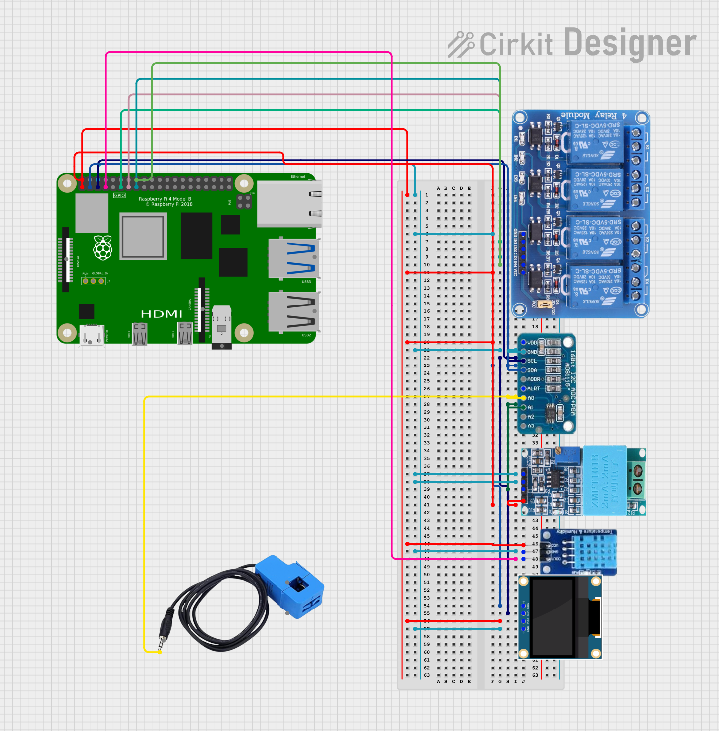
Raspberry Pi 4B-Controlled Relay System with Environmental Sensing and Power Monitoring
Image of smart_power_meter: A project utilizing Raspberry Pi 3B in a practical application
This circuit is designed to interface a Raspberry Pi 4B with various sensors and output devices. It includes a 4-channel relay for controlling external loads, an ADS1115 for analog-to-digital conversion of signals from a current sensor and a ZMPT101B voltage sensor, a DHT11 for temperature and humidity readings, and a 0.96" OLED display for data output. The Raspberry Pi 4B serves as the central controller, managing data acquisition from the sensors, processing the information, and driving the relay and display based on the sensor inputs and programmed logic.
Cirkit Designer LogoOpen Project in Cirkit Designer
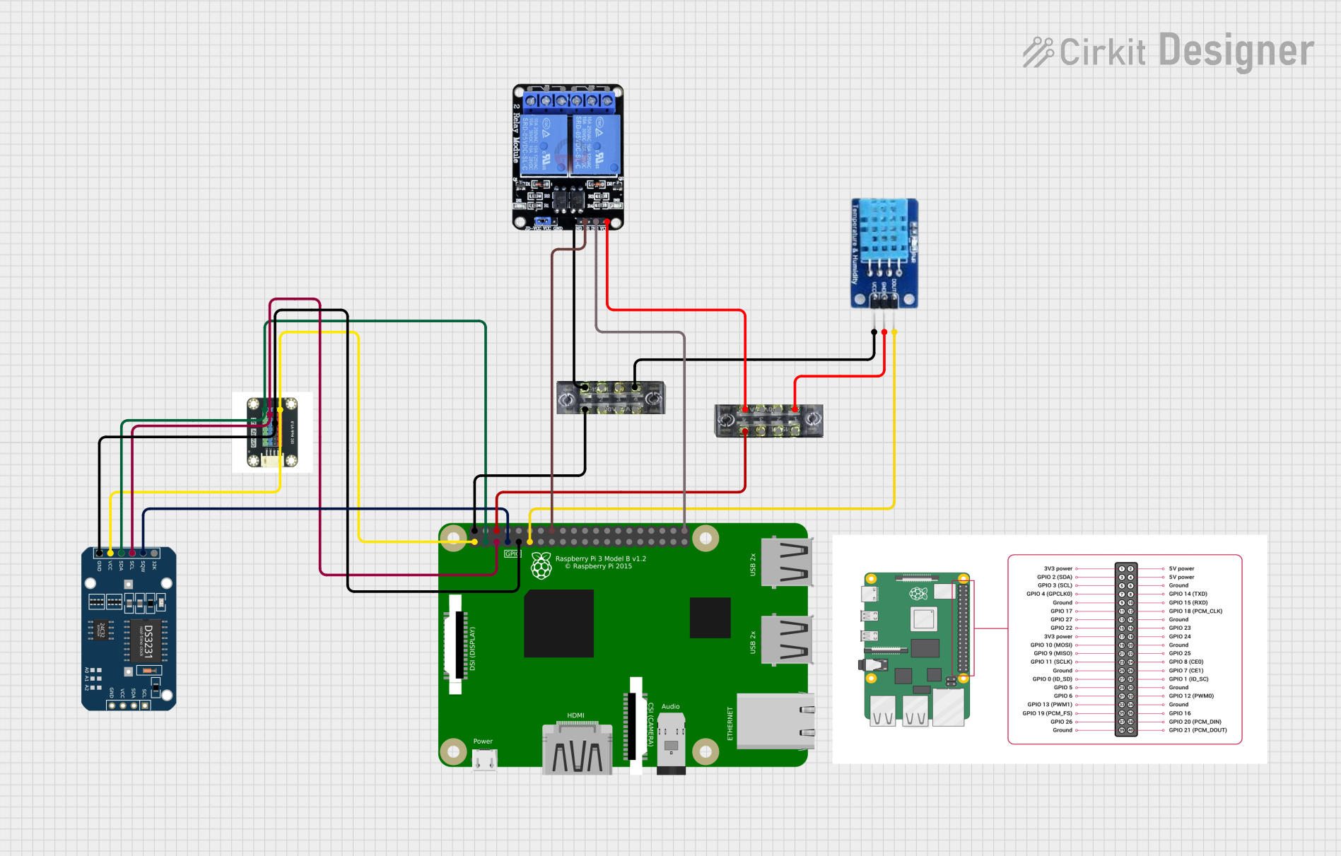
Raspberry Pi 3B Smart Home Automation with Relay Control and DHT11 Sensor
Image of Mycodo v1: A project utilizing Raspberry Pi 3B in a practical application
This circuit integrates a Raspberry Pi 3B with a DHT11 temperature and humidity sensor, a DS3231 RTC module, and a two-channel relay. The Raspberry Pi controls the relay channels and reads data from the DHT11 sensor and the RTC module via GPIO and I2C connections, respectively, enabling environmental monitoring and time-based control applications.
Cirkit Designer LogoOpen Project in Cirkit Designer

Explore Projects Built with Raspberry Pi 3B

Use Cirkit Designer to design, explore, and prototype these projects online. Some projects support real-time simulation. Click "Open Project" to start designing instantly!
Image of Float Robot: A project utilizing Raspberry Pi 3B in a practical application
Raspberry Pi 3B-Based Smart Robot with Sensor Integration
This circuit integrates a Raspberry Pi 3B with various sensors and a motor driver to create a multi-functional system. It includes a DS18B20 temperature sensor, MPU-6050 accelerometer and gyroscope, QMC5883L magnetometer, and an L298N motor driver controlling two DC motors. The Raspberry Pi handles sensor data and motor control through its GPIO pins.
Cirkit Designer LogoOpen Project in Cirkit Designer
Image of wiring: A project utilizing Raspberry Pi 3B in a practical application
Raspberry Pi 4B-Controlled Biometric Access System with Dual Stepper Motor Actuation
This circuit features a Raspberry Pi 4B as the central controller, interfacing with various sensors and modules. It includes a vl53l0xv2 time-of-flight sensor and an AS5600 magnetic encoder for position sensing, both connected via I2C (SDA/SCL lines). The circuit also controls two DRV8825 stepper motor drivers connected to NEMA 17 stepper motors, receives temperature data from a DS18B20 sensor, and communicates with a fingerprint scanner for biometric input. A TM1637 display module is included for user feedback. Power management is handled by a buck converter and a 12V power supply, with the Raspberry Pi and other 3.3V components powered through the buck converter's regulated output.
Cirkit Designer LogoOpen Project in Cirkit Designer
Image of smart_power_meter: A project utilizing Raspberry Pi 3B in a practical application
Raspberry Pi 4B-Controlled Relay System with Environmental Sensing and Power Monitoring
This circuit is designed to interface a Raspberry Pi 4B with various sensors and output devices. It includes a 4-channel relay for controlling external loads, an ADS1115 for analog-to-digital conversion of signals from a current sensor and a ZMPT101B voltage sensor, a DHT11 for temperature and humidity readings, and a 0.96" OLED display for data output. The Raspberry Pi 4B serves as the central controller, managing data acquisition from the sensors, processing the information, and driving the relay and display based on the sensor inputs and programmed logic.
Cirkit Designer LogoOpen Project in Cirkit Designer
Image of Mycodo v1: A project utilizing Raspberry Pi 3B in a practical application
Raspberry Pi 3B Smart Home Automation with Relay Control and DHT11 Sensor
This circuit integrates a Raspberry Pi 3B with a DHT11 temperature and humidity sensor, a DS3231 RTC module, and a two-channel relay. The Raspberry Pi controls the relay channels and reads data from the DHT11 sensor and the RTC module via GPIO and I2C connections, respectively, enabling environmental monitoring and time-based control applications.
Cirkit Designer LogoOpen Project in Cirkit Designer

Technical Specifications

The Raspberry Pi 3B offers the following key technical details:

Specification Details
Processor Quad-core ARM Cortex-A53, 1.2GHz
RAM 1GB LPDDR2
Storage MicroSD card slot
Connectivity 802.11n Wi-Fi, Bluetooth 4.1, Ethernet
USB Ports 4x USB 2.0
GPIO Pins 40-pin header
Video Output HDMI, Composite RCA
Audio Output 3.5mm jack, HDMI
Power Supply 5V/2.5A via micro-USB
Dimensions 85.6mm x 56.5mm x 17mm
Operating System Raspbian (or other Linux-based OS)

GPIO Pin Configuration

The Raspberry Pi 3B features a 40-pin GPIO header for hardware interfacing. Below is the pinout configuration:

Pin Number Pin Name Description
1 3.3V Power 3.3V power supply
2 5V Power 5V power supply
3 GPIO2 (SDA1) I2C Data
4 5V Power 5V power supply
5 GPIO3 (SCL1) I2C Clock
6 Ground Ground
7 GPIO4 General-purpose I/O
8 GPIO14 (TXD) UART Transmit
9 Ground Ground
10 GPIO15 (RXD) UART Receive
... ... ... (Refer to official documentation for full pinout)

Usage Instructions

Setting Up the Raspberry Pi 3B

  1. Prepare the MicroSD Card:
    • Download the Raspberry Pi OS (Raspbian) from the official Raspberry Pi website.
    • Use a tool like Balena Etcher to flash the OS image onto a microSD card.
  2. Connect Peripherals:
    • Insert the microSD card into the Raspberry Pi.
    • Connect a keyboard, mouse, and HDMI display.
    • Optionally, connect to a network via Ethernet or use the built-in Wi-Fi.
  3. Power On:
    • Connect a 5V/2.5A power supply via the micro-USB port.
    • The Raspberry Pi will boot into the OS.

Using GPIO Pins

The GPIO pins can be used to interface with external hardware such as LEDs, sensors, and motors. Below is an example of controlling an LED using Python:


Import the GPIO library

import RPi.GPIO as GPIO import time

Set the GPIO mode to BCM (Broadcom pin numbering)

GPIO.setmode(GPIO.BCM)

Define the GPIO pin for the LED

LED_PIN = 18

Set up the LED pin as an output

GPIO.setup(LED_PIN, GPIO.OUT)

Blink the LED in a loop

try: while True: GPIO.output(LED_PIN, GPIO.HIGH) # Turn the LED on time.sleep(1) # Wait for 1 second GPIO.output(LED_PIN, GPIO.LOW) # Turn the LED off time.sleep(1) # Wait for 1 second except KeyboardInterrupt: # Clean up GPIO settings on exit GPIO.cleanup()


Best Practices

  • Always shut down the Raspberry Pi properly before disconnecting power to avoid corrupting the microSD card.
  • Use a high-quality power supply to ensure stable operation.
  • Avoid directly connecting high-current devices to GPIO pins; use transistors or relays instead.
  • Use resistors when connecting LEDs or other components to GPIO pins to prevent damage.

Troubleshooting and FAQs

Common Issues

  1. The Raspberry Pi does not boot:

    • Ensure the microSD card is properly inserted and contains a valid OS image.
    • Check the power supply for sufficient voltage and current (5V/2.5A recommended).
  2. Wi-Fi connectivity issues:

    • Verify the Wi-Fi credentials are correct.
    • Ensure the Raspberry Pi is within range of the Wi-Fi router.
  3. GPIO pins not working:

    • Double-check the pin numbering mode (BCM vs. BOARD) in your code.
    • Ensure the GPIO pins are not damaged or shorted.
  4. Overheating:

    • Use a heatsink or fan if the Raspberry Pi is running under heavy load for extended periods.

FAQs

Q: Can I power the Raspberry Pi 3B via GPIO pins?
A: Yes, you can power the Raspberry Pi through the 5V and GND GPIO pins, but this bypasses the onboard voltage regulation and protection. Use this method with caution.

Q: What is the maximum current output of the GPIO pins?
A: Each GPIO pin can source/sink a maximum of 16mA, with a total limit of 50mA across all GPIO pins.

Q: Can I use the Raspberry Pi 3B for AI/ML projects?
A: Yes, the Raspberry Pi 3B can run lightweight AI/ML models using frameworks like TensorFlow Lite or OpenCV, but performance may be limited compared to more powerful hardware.

Q: How do I update the Raspberry Pi OS?
A: Run the following commands in the terminal:

sudo apt update
sudo apt full-upgrade

By following this documentation, you can effectively set up and use the Raspberry Pi 3B for a variety of projects.