
How to Use LM386: Examples, Pinouts, and Specs
 Design with LM386 in Cirkit Designer
Introduction
The LM386 is a low-voltage audio power amplifier designed for applications requiring minimal power consumption. It is capable of driving small speakers and headphones, making it ideal for portable, battery-powered devices. The LM386 can amplify audio signals with a default gain of 20, which can be increased up to 200 using external components. Its compact design and ease of use make it a popular choice for audio amplification in hobbyist and professional projects alike.
Explore Projects Built with LM386
 Open Project in Cirkit Designer
 Open Project in Cirkit Designer
 Open Project in Cirkit Designer
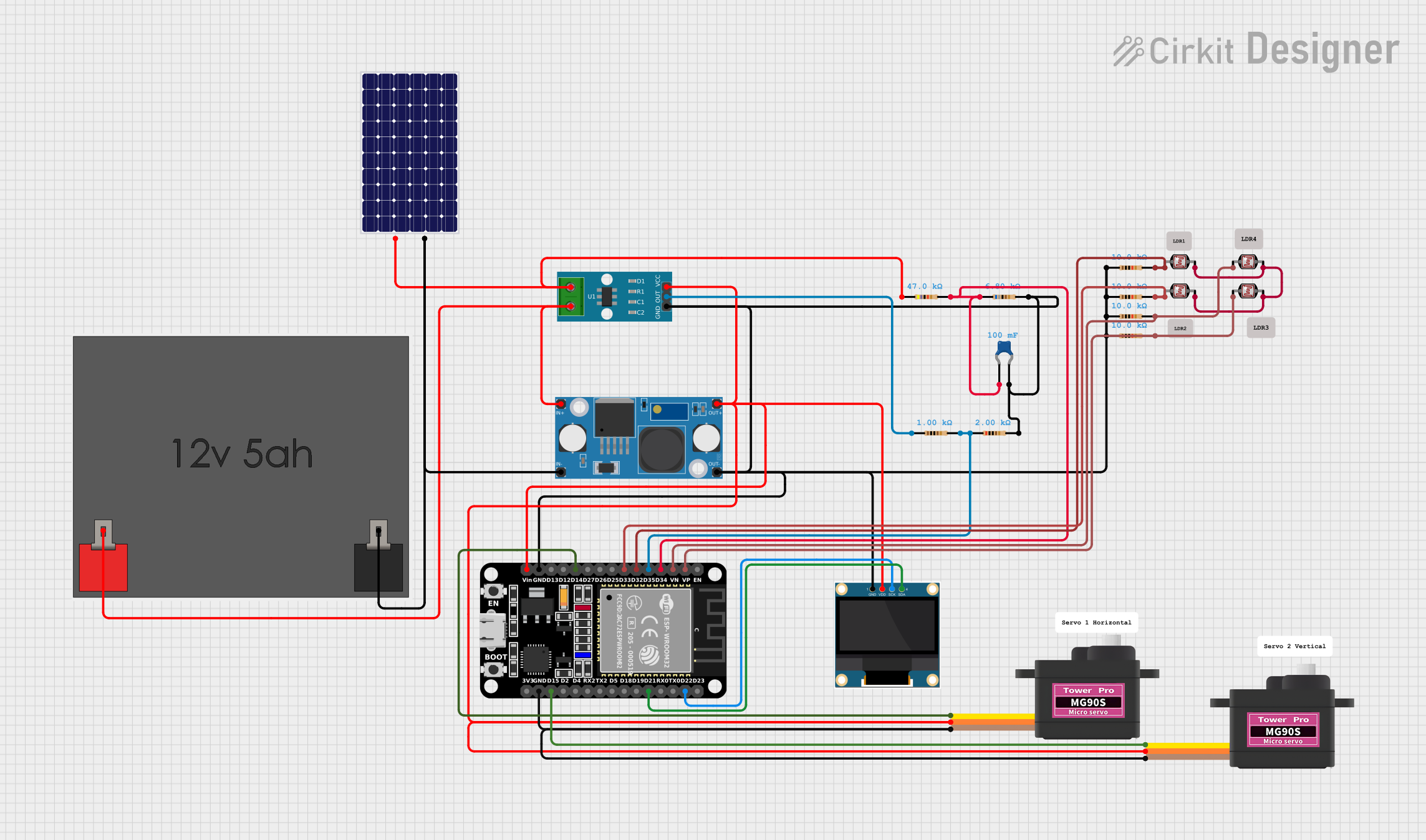 Open Project in Cirkit Designer
Explore Projects Built with LM386
Open Project in Cirkit DesignerOpen Project in Cirkit DesignerOpen Project in Cirkit DesignerOpen Project in Cirkit DesignerCommon Applications
- Portable audio devices
- Intercom systems
- AM/FM radio amplifiers
- DIY audio projects
- Signal amplification for small speakers or headphones
Technical Specifications
Key Technical Details
- Operating Voltage Range: 4V to 12V (or 5V to 18V for LM386N-4 variant)
- Output Power: 0.325W at 8Ω load with 6V supply
- Input Impedance: 50 kΩ
- Voltage Gain: 20 (default), adjustable up to 200
- Quiescent Current: 4 mA (typical)
- Output Load Impedance: 4Ω to 32Ω
- Frequency Response: 300 Hz to 300 kHz
- Total Harmonic Distortion (THD): Less than 0.2% at 1 kHz
Pin Configuration and Descriptions
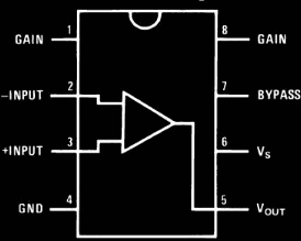
The LM386 is an 8-pin IC. Below is the pinout and description:
| Pin Number | Pin Name | Description |
|---|---|---|
| 1 | Gain | Connect to Pin 8 via a capacitor to increase gain (default gain is 20). |
| 2 | Inverting Input | Negative input for the audio signal. |
| 3 | Non-Inverting Input | Positive input for the audio signal. |
| 4 | Ground (GND) | Connect to the circuit ground. |
| 5 | Output | Amplified audio signal output. |
| 6 | Vcc | Positive power supply (4V to 12V). |
| 7 | Bypass | Connect a capacitor to ground to reduce noise and improve stability. |
| 8 | Gain | Connect to Pin 1 via a capacitor to increase gain (default gain is 20). |
Usage Instructions
How to Use the LM386 in a Circuit
- Power Supply: Connect Pin 6 (Vcc) to a power source between 4V and 12V. Connect Pin 4 to ground.
- Input Signal: Feed the audio signal to Pin 3 (Non-Inverting Input). Pin 2 (Inverting Input) is typically connected to ground.
- Output Signal: Connect the speaker or headphone to Pin 5 (Output) through a coupling capacitor (e.g., 220 µF) to block DC components.
- Gain Adjustment: To increase the gain, connect a capacitor (e.g., 10 µF) between Pins 1 and 8. For the default gain of 20, leave Pins 1 and 8 unconnected.
- Bypass Capacitor: Connect a capacitor (e.g., 10 µF) between Pin 7 (Bypass) and ground to reduce noise and improve stability.
Example Circuit
Below is a basic example of an LM386 circuit for driving an 8Ω speaker:
   +Vcc (4V-12V)
       |
       R (10kΩ)
       |
       +--- Pin 6 (Vcc)
       |
      ---
      --- C1 (10 µF)
       |
       +--- Pin 7 (Bypass)
       |
      ---
      --- GND
       |
Audio Input
   +--- Pin 3 (Non-Inverting Input)
   |
   R (10kΩ)
   |
   +--- Pin 2 (Inverting Input)
   |
   GND
       |
       +--- Pin 4 (GND)
       |
      ---
      --- C2 (220 µF)
       |
Speaker
   +--- Pin 5 (Output)
Arduino Example Code
The LM386 can be used with an Arduino to amplify audio signals. Below is an example of generating a simple tone using the Arduino and driving it through the LM386:
/*
  Example: Generate a tone using Arduino and amplify it with LM386.
  Connect the LM386's input (Pin 3) to Arduino's PWM output (Pin 9).
  Ensure proper connections for power, ground, and output as per the circuit.
*/

const int tonePin = 9; // PWM pin connected to LM386 input

void setup() {
  pinMode(tonePin, OUTPUT); // Set the pin as output
}

void loop() {
  // Generate a 1 kHz tone for 1 second
  tone(tonePin, 1000, 1000);
  delay(2000); // Wait for 2 seconds before repeating
}
Important Considerations
- Use decoupling capacitors (e.g., 0.1 µF) near the power supply pins to reduce noise.
- Avoid exceeding the maximum voltage rating (12V for standard LM386).
- Ensure proper heat dissipation if operating at higher power levels.
- Use shielded cables for input signals to minimize interference.
Troubleshooting and FAQs
Common Issues and Solutions
No Output Signal:
- Verify power supply connections and ensure the voltage is within the operating range.
- Check the input signal and ensure it is properly connected to Pin 3.
- Confirm that the speaker or headphone is connected to Pin 5 through a coupling capacitor.
Distorted Audio:
- Ensure the input signal amplitude is not too high, as it may cause clipping.
- Check the load impedance; it should match the recommended range (4Ω to 32Ω).
- Add a bypass capacitor (e.g., 10 µF) to Pin 7 to reduce noise.
Excessive Noise:
- Use a bypass capacitor on Pin 7 and decoupling capacitors near the power supply.
- Ensure proper grounding and avoid long, unshielded input cables.
Overheating:
- Verify that the load impedance is not too low.
- Reduce the supply voltage if operating near the maximum power output.
FAQs
Q1: Can I use the LM386 to drive a 4Ω speaker?
A1: Yes, the LM386 can drive a 4Ω speaker, but ensure the supply voltage does not exceed 9V to avoid overheating.
Q2: How do I increase the gain of the LM386?
A2: Connect a capacitor (e.g., 10 µF) between Pins 1 and 8 to increase the gain up to 200.
Q3: What is the purpose of the bypass capacitor on Pin 7?
A3: The bypass capacitor reduces noise and improves the stability of the amplifier.
Q4: Can I use the LM386 with a 3.3V power supply?
A4: No, the minimum operating voltage for the LM386 is 4V. Use a power supply within the 4V to 12V range.