
How to Use power supply 24vdc: Examples, Pinouts, and Specs
 Design with power supply 24vdc in Cirkit Designer
Introduction
A power supply 24VDC is an electronic device that converts alternating current (AC) voltage from a mains power source into a stable 24V direct current (DC) output. This component is essential for powering a wide range of electronic devices, industrial equipment, and control systems that require a reliable 24V DC power source.
Explore Projects Built with power supply 24vdc
 Open Project in Cirkit Designer
 Open Project in Cirkit Designer
 Open Project in Cirkit Designer
 Open Project in Cirkit Designer
Explore Projects Built with power supply 24vdc
Open Project in Cirkit DesignerOpen Project in Cirkit DesignerOpen Project in Cirkit DesignerOpen Project in Cirkit DesignerCommon Applications and Use Cases
- Industrial automation systems
- Motor controllers and actuators
- LED lighting systems
- Microcontroller-based projects
- Sensors and instrumentation
- Communication equipment
Technical Specifications
Below are the key technical details for a typical 24VDC power supply:
| Parameter | Specification |
|---|---|
| Input Voltage Range | 100-240V AC, 50/60Hz |
| Output Voltage | 24V DC ± 1% |
| Output Current | 1A to 10A (varies by model) |
| Power Rating | 24W to 240W (depending on model) |
| Efficiency | ≥ 85% |
| Ripple and Noise | ≤ 120mVp-p |
| Operating Temperature | -10°C to +50°C |
| Protection Features | Overvoltage, Overcurrent, Short Circuit |
| Cooling Method | Natural convection or fan-cooled |
| Dimensions | Varies by model (e.g., 110mm x 78mm x 36mm) |
Pin Configuration and Descriptions
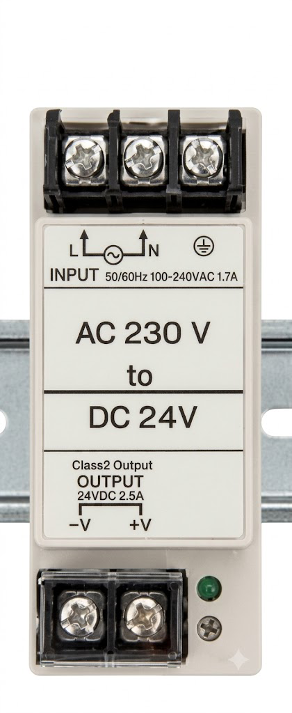
The power supply typically has input and output terminals for wiring. Below is a general description:
| Pin/Terminal | Label | Description |
|---|---|---|
| 1 | L | Live AC input (mains power) |
| 2 | N | Neutral AC input (mains power) |
| 3 | GND | Earth/ground connection |
| 4 | +V | Positive 24V DC output |
| 5 | -V | Negative 24V DC output (ground for DC load) |
Note: Always refer to the specific datasheet of your power supply model for exact pin configurations.
Usage Instructions
How to Use the Component in a Circuit
Wiring the Input:
- Connect the
Lterminal to the live wire of the AC mains supply. - Connect the
Nterminal to the neutral wire of the AC mains supply. - If available, connect the
GNDterminal to the earth/ground wire for safety.
- Connect the
Wiring the Output:
- Connect the
+Vterminal to the positive input of your load or circuit. - Connect the
-Vterminal to the ground or negative input of your load or circuit.
- Connect the
Powering On:
- Ensure all connections are secure and insulated.
- Turn on the AC mains supply to power the device.
Load Considerations:
- Ensure the total current drawn by the connected load does not exceed the rated output current of the power supply.
- Use appropriate fuses or circuit breakers for additional protection.
Important Considerations and Best Practices
- Ventilation: Ensure adequate airflow around the power supply to prevent overheating.
- Mounting: Secure the power supply in a stable position, away from moisture and excessive vibration.
- Polarity: Double-check the polarity of the output connections to avoid damaging your load.
- Isolation: Use proper isolation techniques when interfacing with sensitive circuits.
- Testing: Use a multimeter to verify the output voltage before connecting the load.
Example: Connecting to an Arduino UNO
A 24VDC power supply can be used to power an Arduino UNO indirectly via a step-down voltage regulator (e.g., LM2596) to convert 24V to 5V. Below is an example circuit and Arduino code:
Circuit Setup
- Connect the
+Vand-Vterminals of the power supply to the input of the step-down regulator. - Adjust the regulator to output 5V DC.
- Connect the 5V output of the regulator to the Arduino UNO's
5Vpin andGNDpin.
Arduino Code
// Example code to blink an LED connected to pin 13 of the Arduino UNO
// Ensure the Arduino is powered via the 5V pin from the step-down regulator

void setup() {
  pinMode(13, OUTPUT); // Set pin 13 as an output
}

void loop() {
  digitalWrite(13, HIGH); // Turn the LED on
  delay(1000);            // Wait for 1 second
  digitalWrite(13, LOW);  // Turn the LED off
  delay(1000);            // Wait for 1 second
}
Troubleshooting and FAQs
Common Issues Users Might Face
No Output Voltage:
- Cause: Incorrect wiring or no AC input.
- Solution: Verify the AC input connections and ensure the mains power is on.
Overheating:
- Cause: Insufficient ventilation or excessive load.
- Solution: Ensure proper airflow and reduce the load to within the rated current.
Output Voltage Fluctuations:
- Cause: High ripple or noise due to poor filtering.
- Solution: Add external capacitors or use a higher-quality power supply.
Load Not Powering On:
- Cause: Incorrect polarity or insufficient current.
- Solution: Check the polarity and ensure the load's current requirements are met.
Solutions and Tips for Troubleshooting
- Use a multimeter to measure the input and output voltages.
- Inspect all connections for loose wires or shorts.
- If the power supply has an adjustable output, ensure it is set to 24V.
- Replace the power supply if it shows signs of physical damage or persistent faults.
By following this documentation, you can safely and effectively use a 24VDC power supply in your projects and applications.