How to Use l293d: Examples, Pinouts, and Specs
Introduction
The L293D is a popular Motor Driver IC that allows a microcontroller like the Arduino to drive DC motors and stepper motors. It contains two H-bridge driver circuits in one IC, enabling the control of two DC motors simultaneously in either direction. It is widely used in robotics, small vehicle control, and various automation applications due to its ability to control the speed and direction of motors.
Explore Projects Built with l293d

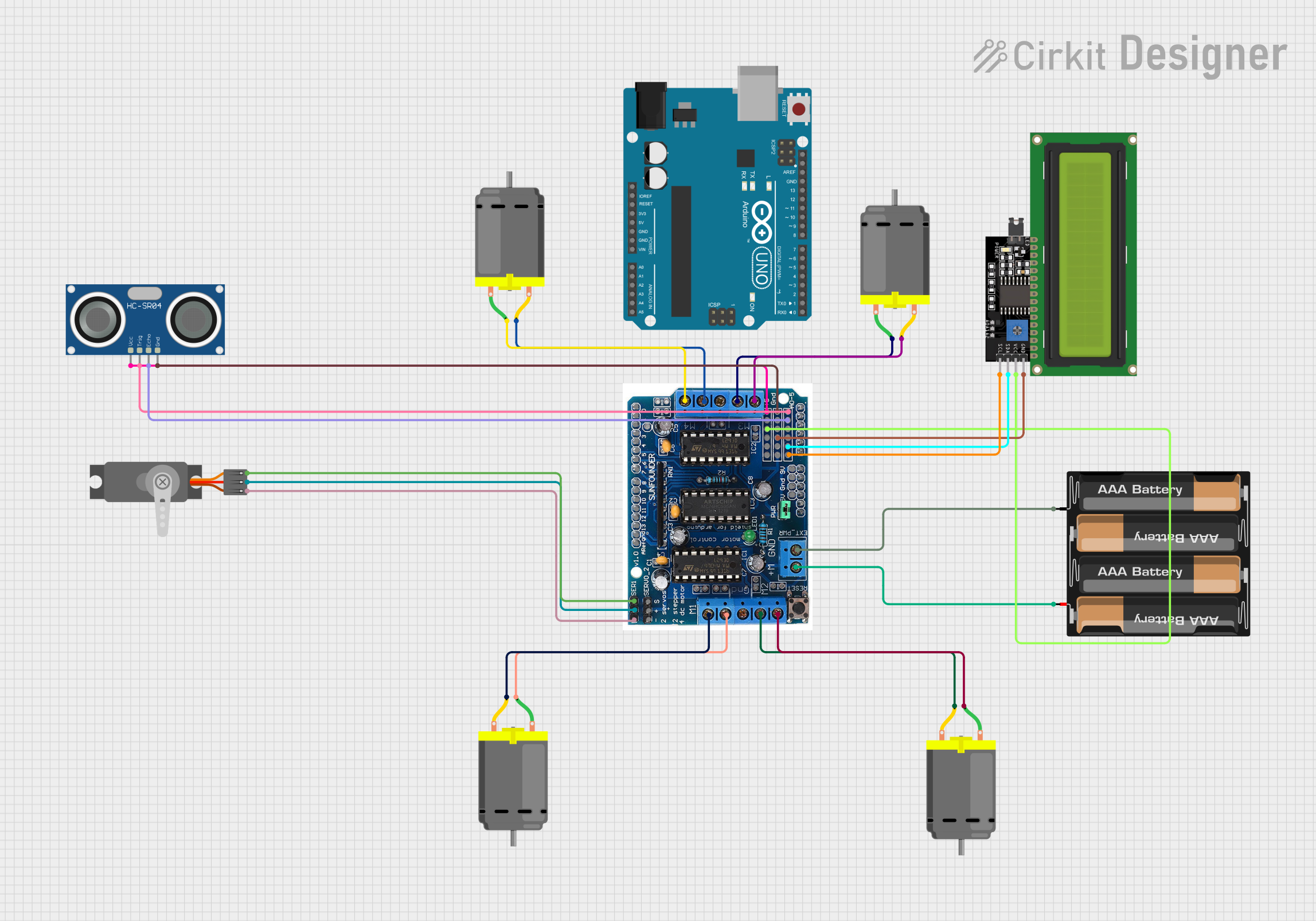
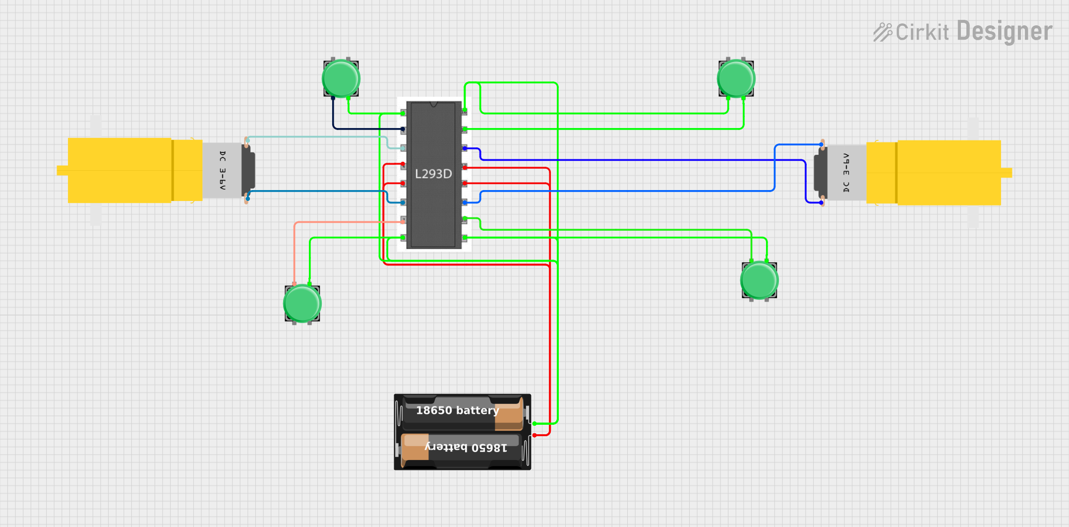
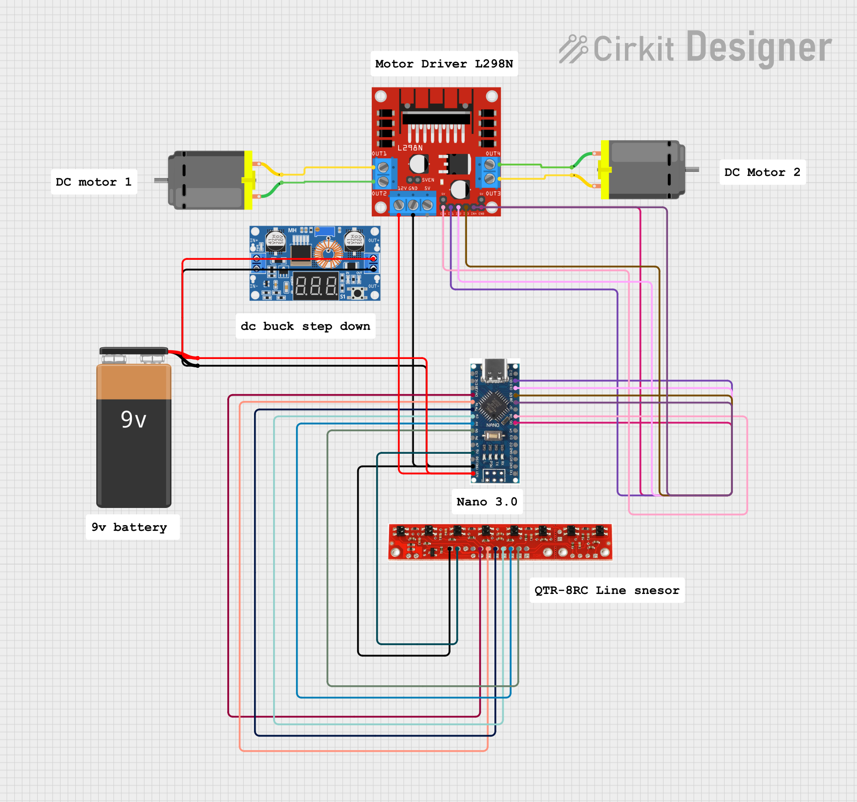
Explore Projects Built with l293d
Technical Specifications
Key Features
- Dual H-Bridge Motor Driver for DC or Steppers
- Operating Voltage: 4.5V to 36V
- Peak Output Current (per channel): 600 mA
- Continuous Output Current (per channel): 300 mA
- Output Clamp Diodes for Inductive Transient Suppression
- Separate Input-Logic Supply
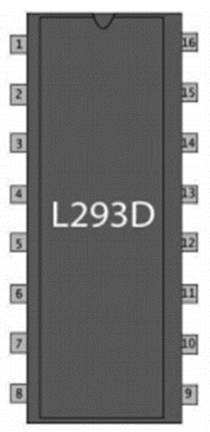
Pin Configuration
| Pin Number | Name | Description |
|---|---|---|
| 1 | 1,2EN | Enable pin for Motor 1; active high |
| 2 | 1A | Input 1 for Motor 1 |
| 3 | 1Y | Output 1 for Motor 1 |
| 4 | GND | Ground (0V) |
| 5 | GND | Ground (0V) |
| 6 | 2Y | Output 2 for Motor 1 |
| 7 | 2A | Input 2 for Motor 1 |
| 8 | VSS | Motor Supply Voltage |
| 9 | 3,4EN | Enable pin for Motor 2; active high |
| 10 | 3A | Input 1 for Motor 2 |
| 11 | 3Y | Output 1 for Motor 2 |
| 12 | GND | Ground (0V) |
| 13 | GND | Ground (0V) |
| 14 | 4Y | Output 2 for Motor 2 |
| 15 | 4A | Input 2 for Motor 2 |
| 16 | VSS | Logic Supply Voltage |
Usage Instructions
Connecting to a DC Motor
- Connect the motor to the L293D output pins (1Y and 2Y for Motor 1, 3Y and 4Y for Motor 2).
- Apply the motor supply voltage (up to 36V) to pin 8 (VSS).
- Connect the ground pins (4, 5, 12, 13) to the system ground.
- Apply a logic supply voltage (up to 36V) to pin 16 (VSS).
- Use the enable pins (1,2EN for Motor 1, 3,4EN for Motor 2) to turn the motor on or off.
- Control the direction by applying logic levels to the input pins (1A and 2A for Motor 1, 3A and 4A for Motor 2).
Arduino Connection Example
// Define the L293D connections to the Arduino
const int motorPin1 = 3; // Input 1 for Motor 1
const int motorPin2 = 4; // Input 2 for Motor 1
const int enablePin1 = 9; // Enable pin for Motor 1

void setup() {
  // Set motor control pins as outputs
  pinMode(motorPin1, OUTPUT);
  pinMode(motorPin2, OUTPUT);
  pinMode(enablePin1, OUTPUT);

  // Enable the motor
  digitalWrite(enablePin1, HIGH);
}

void loop() {
  // Spin the motor in one direction
  digitalWrite(motorPin1, HIGH);
  digitalWrite(motorPin2, LOW);
  delay(2000);

  // Spin the motor in the opposite direction
  digitalWrite(motorPin1, LOW);
  digitalWrite(motorPin2, HIGH);
  delay(2000);

  // Stop the motor
  digitalWrite(motorPin1, LOW);
  digitalWrite(motorPin2, LOW);
  delay(2000);
}
Best Practices
- Use a separate power supply for the motors to prevent noise and voltage drops on the logic side.
- Always use flyback diodes when driving inductive loads to protect the IC from voltage spikes.
- Ensure that the current requirements of your motor do not exceed the IC's maximum current rating.
Troubleshooting and FAQs
Common Issues
- Motor not running: Check if the enable pin is set high and the input pins are receiving the correct logic signals.
- Overheating: Ensure the current draw is within the IC's limits and provide adequate heat dissipation.
- Erratic behavior: Verify that the power supply is stable and that the ground connections are secure.
FAQs
Q: Can the L293D drive stepper motors? A: Yes, the L293D can drive a bipolar stepper motor by controlling the current in each coil in a sequence.
Q: What is the maximum voltage that can be applied to the L293D? A: The maximum motor supply voltage is 36V, and the maximum logic supply voltage is also 36V.
Q: How can I increase the current capability of the L293D? A: To handle more current, you can parallel the output pins of both H-bridges. However, this requires careful thermal management.
Q: Is it necessary to use the enable pins? A: The enable pins allow you to turn the motor on or off without changing the input signals, which can be useful for power management and control logic.
For further assistance, consult the manufacturer's datasheet and application notes.