How to Use sim800Lv2-evb_1_schematic: Examples, Pinouts, and Specs
Introduction
The SIM800L V2 Evaluation Board is a compact GSM/GPRS module designed for wireless communication. It supports functionalities such as SMS, voice calls, and data transmission over 2G networks. The evaluation board simplifies the integration of the SIM800L module into projects by providing a pre-configured schematic with essential components and connections.
This module is widely used in IoT applications, remote monitoring systems, home automation, and any project requiring cellular connectivity. Its small size, low power consumption, and versatile features make it a popular choice for developers and hobbyists.
Explore Projects Built with sim800Lv2-evb_1_schematic


Explore Projects Built with sim800Lv2-evb_1_schematic
Technical Specifications
The SIM800L V2 Evaluation Board is built around the SIM800L GSM/GPRS module and includes additional components to ensure stable operation and easy interfacing. Below are the key technical details:
Key Features
- Operating Voltage: 3.7V to 4.2V (recommended: 4.0V)
- Current Consumption:
- Idle: ~1mA
- Active (GPRS): ~100mA to 250mA
- Peak: ~2A (during transmission bursts)
- Frequency Bands: Quad-band (850/900/1800/1900 MHz)
- Communication Protocols: GSM, GPRS (Class 12)
- Interface: UART (3.3V logic level)
- SIM Card Support: Micro SIM
- Antenna: External antenna via IPX connector
- Operating Temperature: -40°C to +85°C
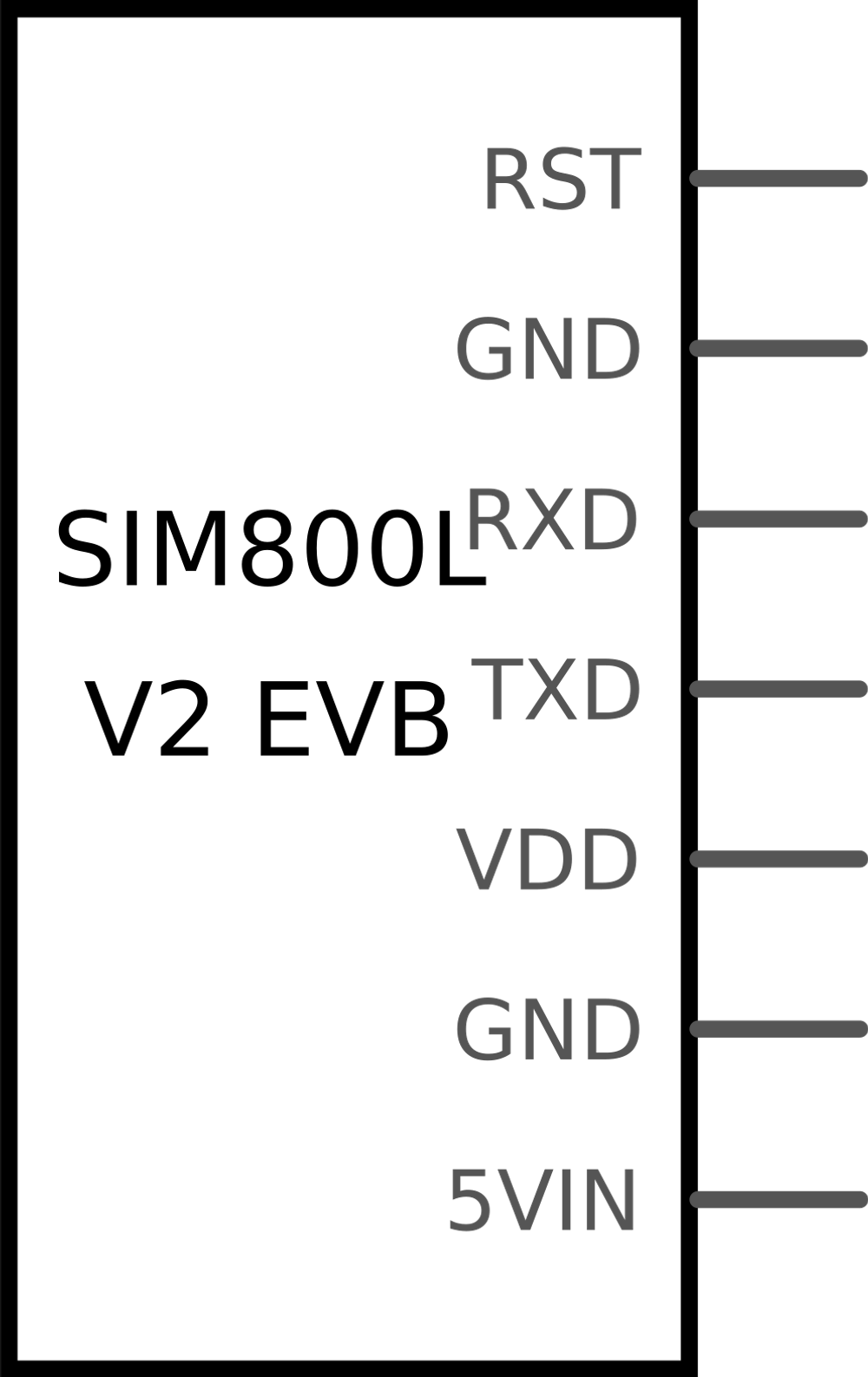
Pin Configuration and Descriptions
The SIM800L V2 Evaluation Board provides several pins for interfacing. Below is the pinout and description:
| Pin Name | Type | Description |
|---|---|---|
| VCC | Power Input | Connect to a 3.7V-4.2V power source (e.g., LiPo battery). |
| GND | Ground | Connect to the ground of the power supply and circuit. |
| TXD | UART Output | Transmit data (connect to RX of the microcontroller). |
| RXD | UART Input | Receive data (connect to TX of the microcontroller). |
| RST | Input | Reset pin (active low). Pull low for at least 100ms to reset the module. |
| NET | Status Output | Network status indicator (blinks to indicate GSM/GPRS status). |
| ANT | Antenna Port | Connect an external antenna via the IPX connector for better signal reception. |
Usage Instructions
How to Use the SIM800L V2 Evaluation Board in a Circuit
Power Supply:
- Use a stable power source capable of providing 3.7V to 4.2V with at least 2A peak current. A LiPo battery is recommended for optimal performance.
- Avoid powering the module directly from a 5V source, as it may damage the module.
Connections:
- Connect the
VCCandGNDpins to the power supply. - Use the
TXDandRXDpins to interface with a microcontroller (e.g., Arduino UNO). Ensure the logic level is 3.3V to avoid damaging the module. - Attach an external antenna to the
ANTport for reliable network connectivity.
- Connect the
SIM Card:
- Insert a micro SIM card into the slot on the evaluation board. Ensure the SIM card is activated and has sufficient balance for SMS, calls, or data usage.
UART Communication:
- Configure the UART interface of your microcontroller to communicate with the SIM800L module. The default baud rate is 9600 bps.
Initialization:
- After powering on, wait for the
NETpin to blink slowly, indicating a successful network connection.
- After powering on, wait for the
Example: Connecting to an Arduino UNO
Below is an example of how to use the SIM800L V2 Evaluation Board with an Arduino UNO to send an SMS:
Circuit Diagram
- Connect
VCCto a 3.7V-4.2V power source. - Connect
GNDto the Arduino's GND. - Connect
TXDto Arduino pin 10 (RX). - Connect
RXDto Arduino pin 11 (TX) via a voltage divider to step down the 5V signal to 3.3V.
Arduino Code
#include <SoftwareSerial.h>

// Define RX and TX pins for SoftwareSerial
SoftwareSerial sim800l(10, 11); // RX, TX

void setup() {
  // Initialize serial communication with the SIM800L module
  sim800l.begin(9600);
  Serial.begin(9600);

  // Wait for the module to initialize
  Serial.println("Initializing SIM800L...");
  delay(1000);

  // Send an AT command to check communication
  sim800l.println("AT");
  delay(1000);
  while (sim800l.available()) {
    Serial.write(sim800l.read()); // Print response to Serial Monitor
  }

  // Send an SMS
  sendSMS("+1234567890", "Hello from SIM800L!");
}

void loop() {
  // Nothing to do here
}

void sendSMS(String phoneNumber, String message) {
  sim800l.println("AT+CMGF=1"); // Set SMS mode to text
  delay(1000);
  sim800l.println("AT+CMGS=\"" + phoneNumber + "\""); // Set recipient
  delay(1000);
  sim800l.print(message); // Write the message
  delay(1000);
  sim800l.write(26); // Send Ctrl+Z to send the SMS
  delay(5000);
  Serial.println("SMS sent!");
}
Important Considerations
- Ensure the power supply is stable and capable of handling the module's peak current requirements.
- Use a level shifter or voltage divider when interfacing with 5V logic devices like the Arduino UNO.
- Place the antenna in an open area for better signal reception.
Troubleshooting and FAQs
Common Issues and Solutions
Module Not Powering On:
- Ensure the power supply provides 3.7V-4.2V with sufficient current (2A peak).
- Check the connections to the
VCCandGNDpins.
No Network Connection:
- Verify that the SIM card is properly inserted and activated.
- Check the antenna connection and ensure good signal reception.
- Confirm that the module supports the frequency bands of your local network.
No Response to AT Commands:
- Ensure the UART connections (TXD and RXD) are correct.
- Verify the baud rate is set to 9600 bps.
- Check for voltage level mismatches between the module and the microcontroller.
Module Resets During Operation:
- This is often caused by insufficient power. Use a capacitor (e.g., 1000µF) across the power supply to stabilize it.
FAQs
Can I power the module with 5V?
No, the module requires 3.7V-4.2V. Use a step-down regulator if your power source is 5V.What is the default baud rate of the SIM800L module?
The default baud rate is 9600 bps.How do I reset the module?
Pull theRSTpin low for at least 100ms to reset the module.Can I use the module for 3G or 4G networks?
No, the SIM800L only supports 2G networks (GSM/GPRS).
By following this documentation, you can effectively integrate the SIM800L V2 Evaluation Board into your projects for reliable GSM/GPRS communication.