The M251 (TM251MESC) is a compact and versatile programmable logic controller (PLC) manufactured by Schneider Electric. It is designed for industrial automation and control applications, offering high performance, flexibility, and connectivity. The M251 is particularly suited for applications requiring distributed control, remote monitoring, and integration with industrial networks.
Explore Projects Built with M251
Use Cirkit Designer to design, explore, and prototype these projects online. Some projects support real-time simulation. Click "Open Project" to start designing instantly!
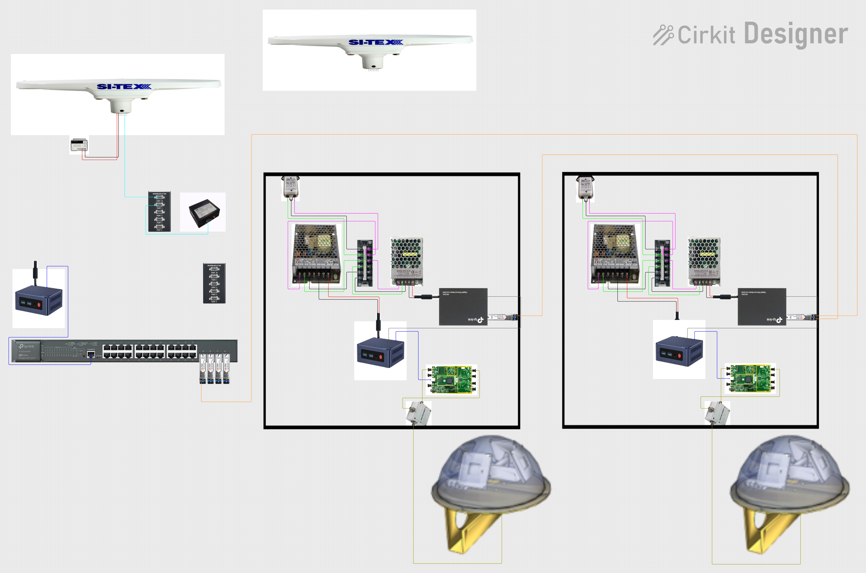
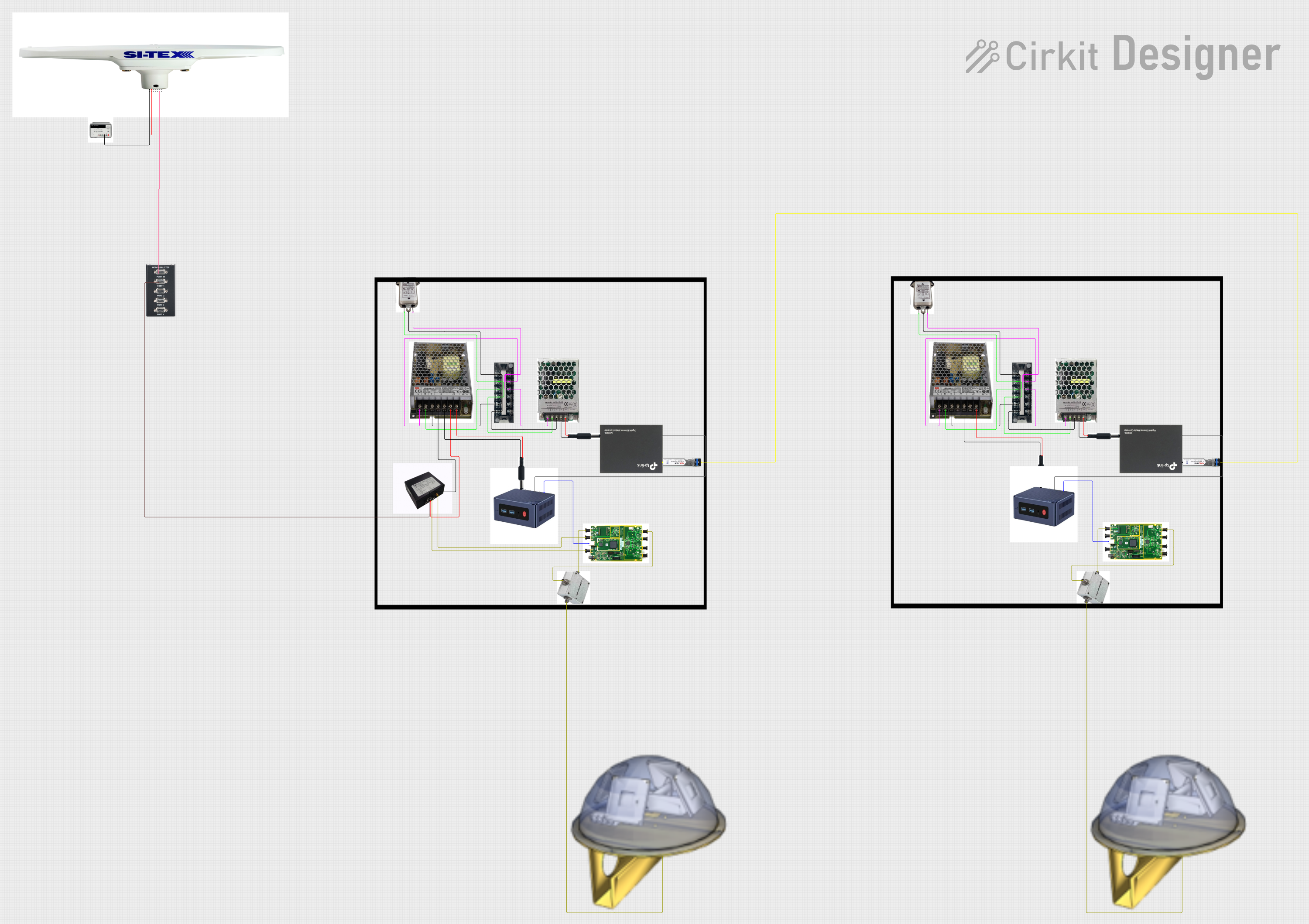
This circuit appears to be a complex system involving power supply management, GPS and timing synchronization, and data communication. It includes a SI-TEX G1 Satellite Compass for GPS data, an XHTF1021 Atomic Rubidium Clock for precise timing, and Ettus USRP B200 units for software-defined radio communication. Power is supplied through various SMPS units and distributed via terminal blocks and DC jacks. Data communication is facilitated by Beelink MINI S12 N95 computers, RS232 splitters, and a 1000BASE-T Media Converter for network connectivity. RF Directional Couplers are used to interface antennas with the USRP units, and the entire system is likely contained within cases for protection and organization.
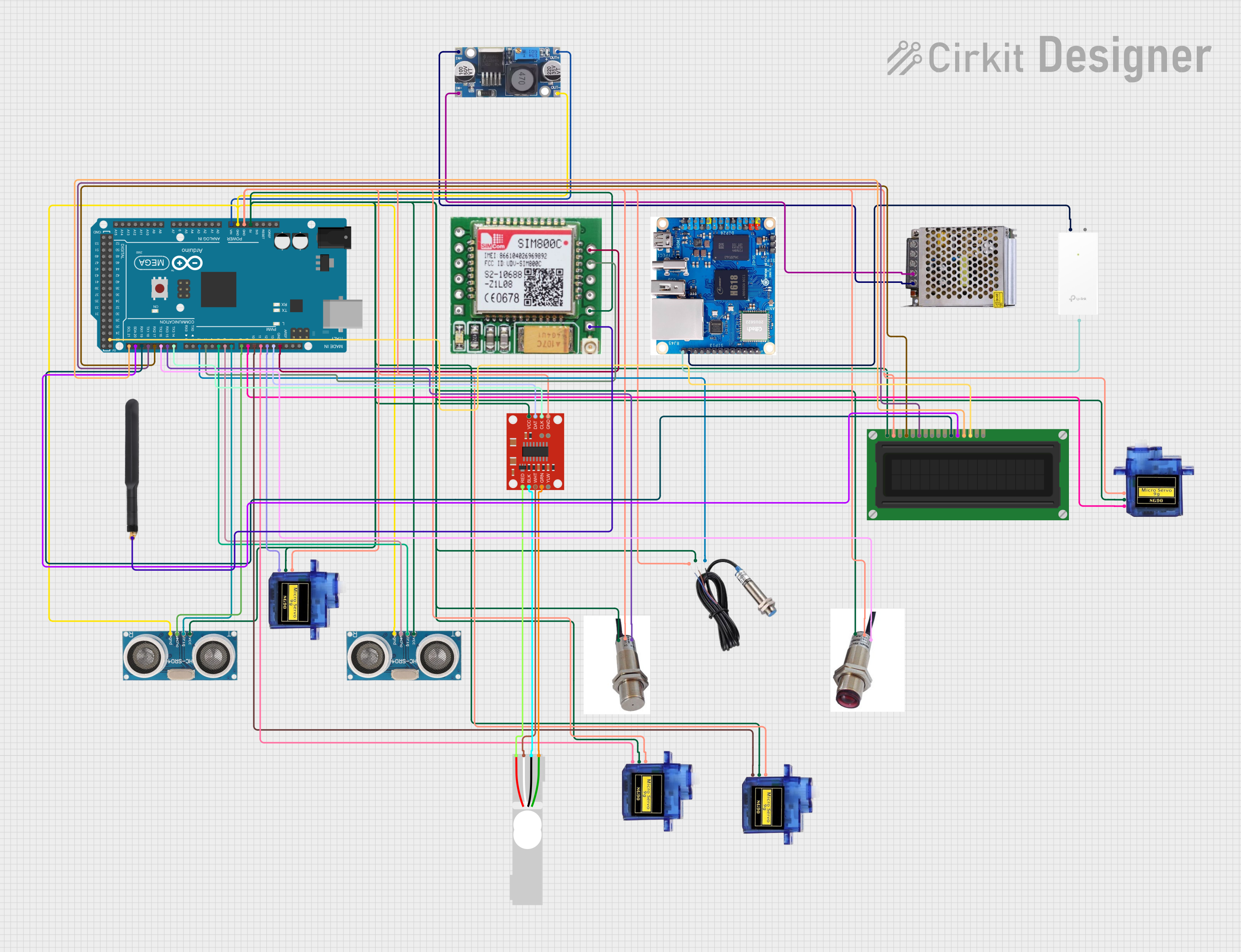
This circuit is a reverse vending machine for plastic bottles and cans, utilizing an Arduino Mega 2560 to interface with various sensors and actuators. It includes ultrasonic sensors for distance measurement, a load cell for weight measurement, micro servos for actuation, and a GSM module for communication. The system also features an LCD display for user interaction and uses inductive and photoelectric sensors for object detection.
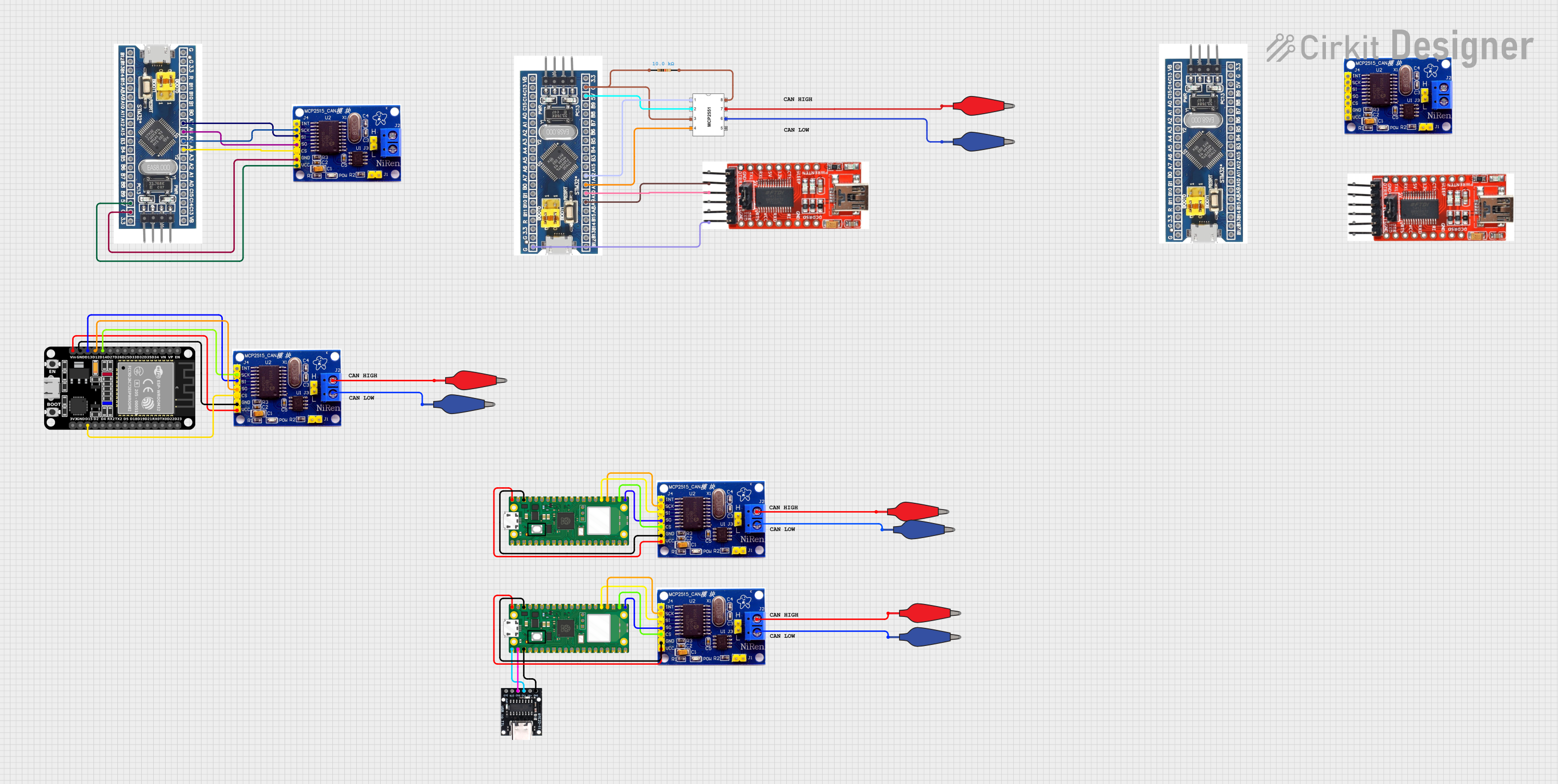
This circuit integrates multiple microcontrollers (STM32F103C8T6, ESP32, and Raspberry Pi Pico W) with MCP2515 CAN controllers to facilitate CAN bus communication. The microcontrollers are connected to the MCP2515 modules via SPI interfaces, and the circuit includes USB-to-serial converters for programming and debugging purposes.
This circuit comprises a satellite compass, a mini PC, two GPS antennas, power supplies, a network switch, media converters, and an atomic rubidium clock. The satellite compass is powered by a triple output DC power supply and interfaces with an RS232 splitter for 1PPS signals. The mini PCs are connected to the USRP B200 devices via USB for data and power, and to media converters via Ethernet, which in turn connect to a network switch using fiber optic links. The antennas are connected to the USRP B200s through RF directional couplers, and the atomic clock provides a 1PPS input to the RS232 splitter.
Integration with Modbus, Ethernet/IP, and other industrial communication protocols
Remote monitoring and data acquisition in smart factories
Technical Specifications
Key Technical Details
Manufacturer: Schneider Electric
Part Number: TM251MESC
Processor: ARM Cortex-A9, 600 MHz
Memory:
64 MB RAM
128 MB Flash memory
Power Supply: 24 V DC (±20%)
Communication Ports:
2x Ethernet ports (10/100 Mbps)
1x Serial port (RS-232/RS-485)
1x USB port (for programming and diagnostics)
Supported Protocols: Modbus TCP, Ethernet/IP, OPC UA, and more
Operating Temperature: -10°C to +55°C
Dimensions: 90 x 95 x 70 mm (H x W x D)
Mounting: DIN rail
Pin Configuration and Descriptions
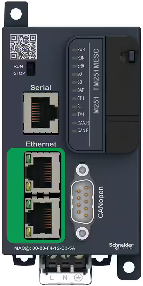
The M251 (TM251MESC) has multiple ports and terminals for power, communication, and I/O connections. Below is a summary of the key pin configurations:
Power Supply Terminals
Pin Number
Description
Notes
1
+24 V DC Input
Connect to a 24 V DC power source.
2
0 V (Ground)
Common ground for the power supply.
Ethernet Ports
Port Number
Description
Notes
ETH1
Ethernet Port 1
For network communication.
ETH2
Ethernet Port 2
Supports daisy-chaining.
Serial Port (RS-232/RS-485)
Pin Number
Description
Notes
TXD
Transmit Data
RS-232 communication.
RXD
Receive Data
RS-232 communication.
A
Data+ (RS-485)
RS-485 communication.
B
Data- (RS-485)
RS-485 communication.
USB Port
Port Number
Description
Notes
USB
USB Programming Port
For programming and diagnostics.
Usage Instructions
How to Use the M251 in a Circuit
Power Connection:
Connect the +24 V DC power supply to the power input terminals (Pin 1 and Pin 2).
Ensure the power supply is stable and within the specified voltage range (24 V ±20%).
Communication Setup:
Use the Ethernet ports (ETH1 and ETH2) to connect the M251 to your industrial network.
Configure the IP address and communication settings using Schneider Electric's EcoStruxure Machine Expert software.
Programming:
Connect the M251 to your PC using the USB programming port.
Use EcoStruxure Machine Expert to write and upload your control logic.
I/O Configuration:
Connect external sensors, actuators, or other devices to the M251's I/O modules (if applicable).
Configure the I/O settings in the software to match your application requirements.
Testing and Deployment:
Test the system functionality in a controlled environment.
Deploy the M251 in your industrial setup and monitor its performance.
Important Considerations and Best Practices
Always use a regulated 24 V DC power supply to avoid damage to the device.
Ensure proper grounding to minimize electrical noise and interference.
Use shielded cables for communication ports to improve signal integrity.
Regularly update the firmware to benefit from the latest features and security patches.
Follow all safety guidelines and standards for industrial automation systems.
Example Code for Modbus Communication with Arduino UNO
Below is an example of how to communicate with the M251 using Modbus RTU protocol and an Arduino UNO:
#include <ModbusMaster.h>

// Instantiate ModbusMaster object
ModbusMaster node;

void setup() {
  // Initialize serial communication for debugging
  Serial.begin(9600);

  // Initialize Modbus communication (RS-485)
  node.begin(1, Serial); // Slave ID = 1

  // Configure RS-485 communication settings
  Serial.begin(19200, SERIAL_8N1); // 19200 baud, 8 data bits, no parity, 1 stop bit
}

void loop() {
  uint8_t result;
  uint16_t data;

  // Read a holding register (e.g., register 40001)
  result = node.readHoldingRegisters(0x0000, 1);

  if (result == node.ku8MBSuccess) {
    data = node.getResponseBuffer(0);
    Serial.print("Register Value: ");
    Serial.println(data);
  } else {
    Serial.print("Error Code: ");
    Serial.println(result);
  }

  delay(1000); // Wait 1 second before the next request
}
Troubleshooting and FAQs
Common Issues and Solutions
Device Not Powering On:
Cause: Incorrect power supply voltage or loose connections.
Solution: Verify the power supply voltage (24 V ±20%) and check all connections.
Communication Failure:
Cause: Incorrect IP address or communication settings.
Solution: Double-check the network configuration in EcoStruxure Machine Expert.
Program Upload Fails:
Cause: USB cable not connected properly or driver issues.
Solution: Ensure the USB cable is securely connected and update the USB driver if necessary.
I/O Modules Not Responding:
Cause: Incorrect wiring or configuration.
Solution: Verify the wiring and ensure the I/O modules are properly configured in the software.
FAQs
Q: Can the M251 be used in harsh environments? A: Yes, the M251 is designed to operate in temperatures ranging from -10°C to +55°C. However, ensure it is installed in a suitable enclosure for protection against dust and moisture.
Q: Does the M251 support remote monitoring? A: Yes, the M251 supports remote monitoring via Ethernet and protocols like Modbus TCP and OPC UA.
Q: Can I expand the I/O capabilities of the M251? A: Yes, the M251 supports expansion modules for additional I/O channels.
Q: What software is required to program the M251? A: Schneider Electric's EcoStruxure Machine Expert software is used for programming and configuration.
This concludes the documentation for the M251 (TM251MESC). For further assistance, refer to the official Schneider Electric user manual or contact their technical support.

 Open Project in Cirkit Designer