How to Use Red momentary switch 32 mm: Examples, Pinouts, and Specs
Introduction
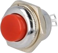
The Red Momentary Switch with a 32 mm diameter is a push-to-make (normally open) switch that closes the circuit only while the button is being pressed and breaks the circuit once the button is released. This type of switch is ideal for applications requiring a temporary action, such as starting a machine, triggering a bell, or input for electronic projects.
Explore Projects Built with Red momentary switch 32 mm
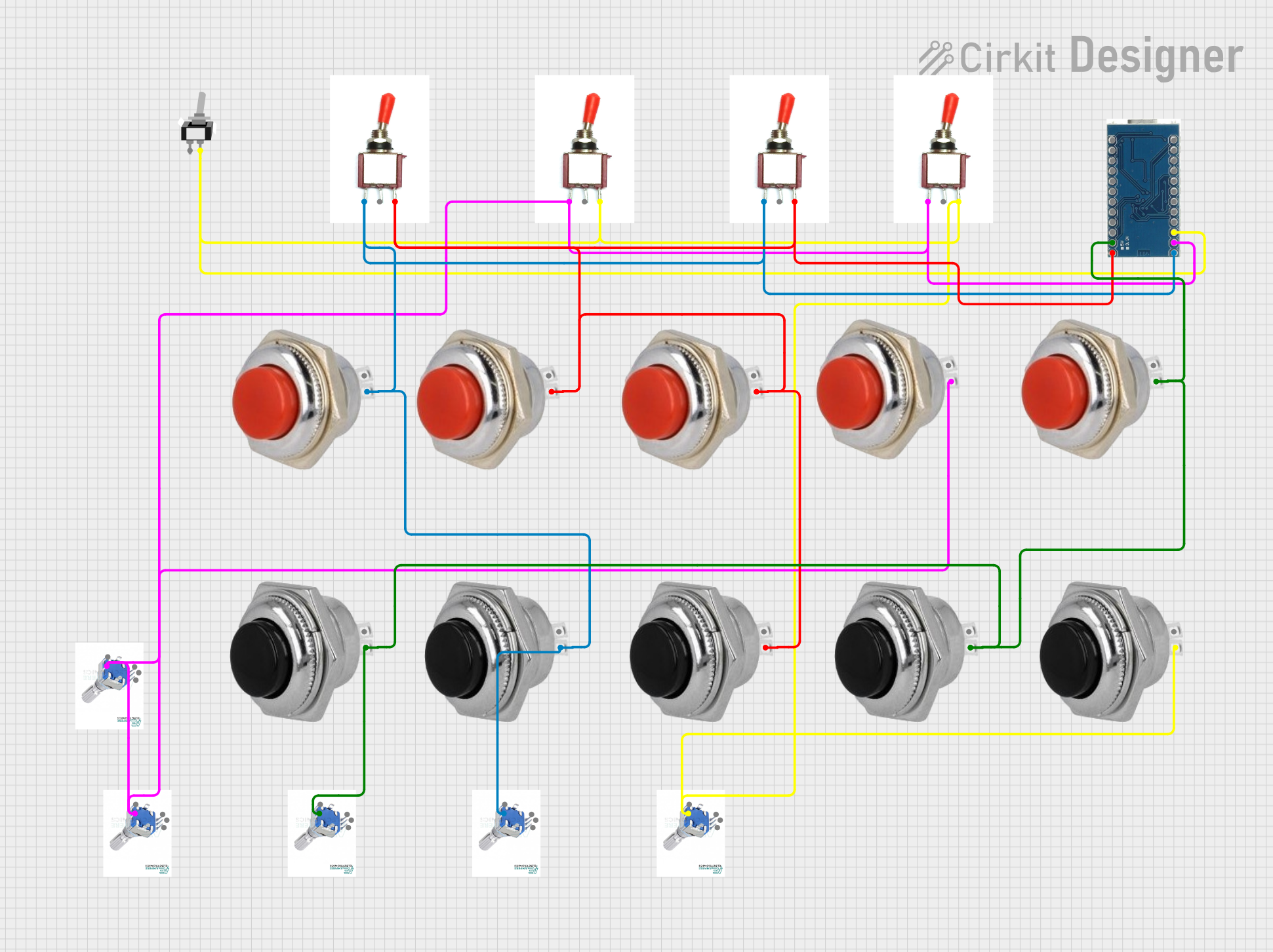
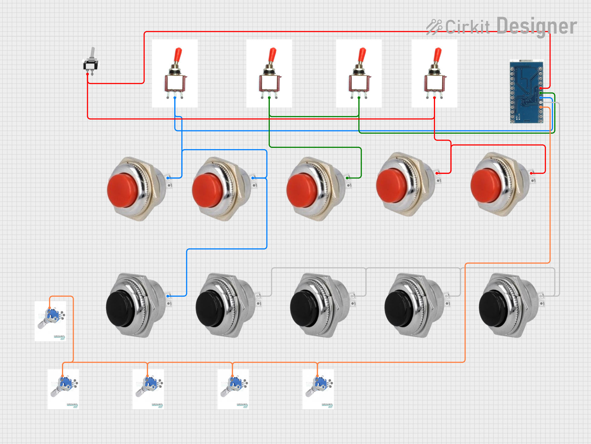

Explore Projects Built with Red momentary switch 32 mm
Common Applications and Use Cases
- Industrial controls
- Consumer electronics
- Interactive displays
- Hobbyist projects, including Arduino-based circuits
Technical Specifications
Key Technical Details
- Switch Type: Momentary, normally open
- Diameter: 32 mm
- Contact Rating: Typically 1-3 A @ 125/250 VAC
- Contact Resistance: <50 mΩ initial
- Insulation Resistance: >100 MΩ at 500 VDC
- Dielectric Strength: 1,000 VAC for 1 minute
- Operating Temperature Range: -20°C to +70°C
- Mechanical Life: >500,000 cycles
- Electrical Life: >100,000 cycles
Pin Configuration and Descriptions
| Pin Number | Description |
|---|---|
| 1 | Normally Open (NO) |
| 2 | Common (COM) |
Usage Instructions
How to Use the Component in a Circuit
- Identify the Pins: Locate the pins labeled as Normally Open (NO) and Common (COM).
- Wiring: Connect the COM pin to one side of the power source or to the signal line that needs to be controlled.
- Load Connection: Connect the NO pin to the load (e.g., LED, relay, or other input devices).
- Testing: Press the switch to ensure that the connection is established and the load operates as expected.
Important Considerations and Best Practices
- Ensure the switch's ratings match the requirements of your application.
- Avoid excessive force to prevent mechanical damage.
- Use a pull-down resistor if the switch is used as an input to a microcontroller to avoid floating inputs.
- For AC applications, ensure proper isolation to prevent electric shock.
Example Code for Arduino UNO
// Define the pin connected to the switch
const int switchPin = 2;

void setup() {
  pinMode(switchPin, INPUT_PULLUP); // Set the switch pin as input with internal pull-up
  Serial.begin(9600);               // Start serial communication at 9600 baud
}

void loop() {
  // Check if the switch is pressed
  if (digitalRead(switchPin) == LOW) {
    // The switch is pressed (circuit closed)
    Serial.println("Switch Pressed");
    // Add code here to perform an action when the switch is pressed
  } else {
    // The switch is not pressed (circuit open)
    Serial.println("Switch Released");
    // Add code here to perform an action when the switch is released
  }
  delay(100); // Debounce delay to avoid flickering
}
Troubleshooting and FAQs
Common Issues Users Might Face
- Switch does not respond: Check the wiring and ensure the connections are secure.
- Intermittent operation: Verify that there is no debris or damage to the switch that could affect its operation.
- Unexpected behavior in digital circuits: Ensure that pull-up or pull-down resistors are used to maintain a stable state when the switch is open.
Solutions and Tips for Troubleshooting
- Double-check the switch's current and voltage ratings against the application's requirements.
- If using with a microcontroller, use the internal pull-up resistor to avoid floating inputs.
- For mechanical issues, inspect the switch for physical damage or wear.
FAQs
Q: Can this switch be used with a DC circuit? A: Yes, the switch can be used with both AC and DC circuits, as long as the voltage and current do not exceed the switch's ratings.
Q: Is debouncing necessary for this switch? A: Yes, debouncing is recommended to ensure stable switch readings, especially in digital applications.
Q: How do I mount this switch? A: The switch typically comes with a threaded body and a nut for mounting through a panel. Ensure the hole in the panel matches the diameter of the switch for a proper fit.