How to Use Ali CC1101: Examples, Pinouts, and Specs
Ali CC1101 Transceiver Module Documentation
1. Introduction
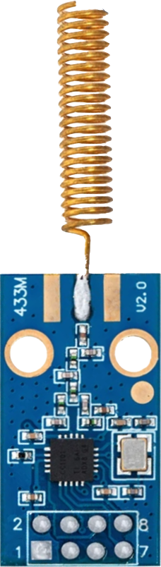
The Ali CC1101 is a low-power, sub-1 GHz transceiver module manufactured by D-SUN. It is designed for low data rate wireless communication and is widely used in applications such as:
- Remote control systems (e.g., garage doors, wireless switches)
- Sensor networks (e.g., IoT devices, environmental monitoring)
- Home automation (e.g., smart lighting, security systems)
- Industrial control systems
The CC1101 offers features like adjustable output power, multiple data rates, and a flexible modulation scheme, making it a versatile choice for wireless communication in the ISM (Industrial, Scientific, and Medical) frequency bands.
2. Technical Specifications
The following table outlines the key technical details of the Ali CC1101 module:
| Parameter | Specification |
|---|---|
| Frequency Range | 300 MHz to 928 MHz (programmable) |
| Modulation | 2-FSK, GFSK, MSK, OOK, ASK |
| Data Rate | 0.6 kbps to 500 kbps |
| Output Power | Programmable from -30 dBm to +10 dBm |
| Supply Voltage | 1.8 V to 3.6 V |
| Current Consumption | 14.7 mA (RX mode), 34.2 mA (TX mode at +10 dBm) |
| Communication Interface | SPI (Serial Peripheral Interface) |
| Operating Temperature | -40°C to +85°C |
| Antenna Interface | 50 Ω impedance |
Pin Configuration and Descriptions
The Ali CC1101 module typically has a 10-pin interface. The pinout and descriptions are as follows:
| Pin | Name | Description |
|---|---|---|
| 1 | GND | Ground connection |
| 2 | VCC | Power supply (1.8 V to 3.6 V) |
| 3 | CSN | SPI chip select (active low) |
| 4 | SCLK | SPI clock input |
| 5 | MOSI | SPI data input (Master Out Slave In) |
| 6 | MISO | SPI data output (Master In Slave Out) |
| 7 | GDO0 | General-purpose digital output 0 (configurable interrupt or status signal) |
| 8 | GDO2 | General-purpose digital output 2 (configurable interrupt or status signal) |
| 9 | ANT | Antenna connection (50 Ω impedance) |
| 10 | NC | Not connected (reserved for future use) |
3. Usage Instructions
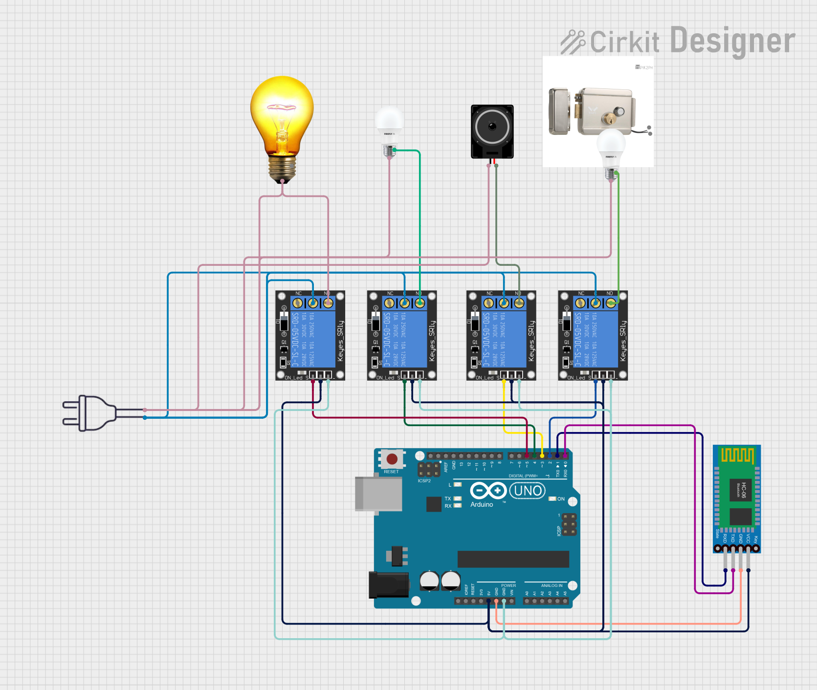
Connecting the CC1101 to an Arduino UNO
To use the Ali CC1101 with an Arduino UNO, follow these steps:
Wiring the Module: Connect the CC1101 module to the Arduino UNO as shown in the table below:
CC1101 Pin Arduino UNO Pin GND GND VCC 3.3V CSN D10 SCLK D13 MOSI D11 MISO D12 GDO0 D2 GDO2 D3 Note: The CC1101 operates at 3.3V. Ensure that the Arduino's 5V logic levels are converted to 3.3V using a level shifter or voltage divider if necessary.
Install Required Libraries: Download and install the ELECHOUSE_CC1101 library from the Arduino Library Manager or GitHub. This library simplifies communication with the CC1101 module.
Basic Arduino Code: Below is an example code to initialize the CC1101 and send a simple message:
#include <ELECHOUSE_CC1101.h> // Include the CC1101 library

void setup() {
  Serial.begin(9600); // Initialize serial communication for debugging
  if (ELECHOUSE_cc1101.getCC1101()) {
    Serial.println("CC1101 initialized successfully!");
  } else {
    Serial.println("CC1101 initialization failed!");
    while (1); // Halt execution if initialization fails
  }

  ELECHOUSE_cc1101.Init(); // Initialize the CC1101 module
  ELECHOUSE_cc1101.setMHZ(433.0); // Set frequency to 433 MHz
}

void loop() {
  const char* message = "Hello, CC1101!";
  ELECHOUSE_cc1101.SendData((byte*)message, strlen(message)); // Send data
  Serial.println("Message sent: Hello, CC1101!");
  delay(1000); // Wait 1 second before sending the next message
}
Important: Ensure the CC1101 module is configured to the same frequency and modulation settings as the receiving device.
Best Practices
- Use a proper 50 Ω antenna for optimal performance.
- Avoid placing the module near high-frequency noise sources (e.g., switching power supplies).
- Use decoupling capacitors (e.g., 0.1 µF) near the VCC pin to reduce power supply noise.
- Ensure the SPI connections are secure and free from interference.
4. Troubleshooting and FAQs
Common Issues and Solutions
| Issue | Possible Cause | Solution |
|---|---|---|
| CC1101 not initializing | Incorrect wiring or power supply | Double-check connections and ensure 3.3V power supply. |
| No data received on the receiver side | Frequency mismatch or poor antenna | Ensure both devices are set to the same frequency and use a proper antenna. |
| Unstable communication | Interference or incorrect modulation settings | Try changing the frequency or modulation scheme. |
| High current consumption | Module stuck in TX mode | Ensure proper SPI communication and send a command to switch to RX mode. |
Frequently Asked Questions
Can the CC1101 operate at 5V?
- No, the CC1101 operates at 1.8V to 3.6V. Use a level shifter for 5V systems.
What is the maximum range of the CC1101?
- The range depends on the antenna, output power, and environment. Typically, it can achieve up to 500 meters in open space.
Can I use multiple CC1101 modules in the same area?
- Yes, but ensure they operate on different frequencies or use unique addresses to avoid interference.
How do I change the frequency of the CC1101?
- Use the
setMHZ()function in the ELECHOUSE_CC1101 library to set the desired frequency.
- Use the
This documentation provides a comprehensive guide to using the Ali CC1101 transceiver module. For further assistance, refer to the official datasheet or the ELECHOUSE_CC1101 library documentation.
Explore Projects Built with Ali CC1101


Explore Projects Built with Ali CC1101