How to Use USB A 5V step down: Examples, Pinouts, and Specs
Introduction
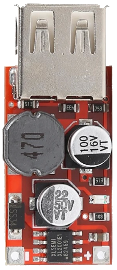
The USB A 5V Step Down is a voltage regulator module designed to convert a higher input voltage (e.g., 6V–24V) into a stable 5V output. This component is commonly used to power USB devices, such as smartphones, microcontrollers, and other USB-powered peripherals, from non-USB power sources like batteries, solar panels, or DC power supplies. Its compact design and ease of use make it a popular choice for DIY electronics projects and portable power solutions.
Explore Projects Built with USB A 5V step down


Explore Projects Built with USB A 5V step down
Common Applications
- Powering USB devices from a car battery or other DC sources.
- Supplying 5V to microcontrollers like Arduino or Raspberry Pi.
- Portable charging stations for USB-powered gadgets.
- Integrating USB power into custom electronics projects.
Technical Specifications
Below are the key technical details of the USB A 5V Step Down module:
| Parameter | Specification |
|---|---|
| Input Voltage Range | 6V–24V DC |
| Output Voltage | 5V DC (regulated) |
| Output Current | Up to 3A (depending on input source) |
| Efficiency | Up to 92% |
| USB Port Type | USB Type-A |
| Dimensions | Varies by model (e.g., 25mm x 15mm) |
| Protection Features | Overcurrent, overvoltage, and short-circuit protection |
Pin Configuration and Descriptions
The USB A 5V Step Down module typically has the following input and output connections:
| Pin/Port | Description |
|---|---|
| VIN+ | Positive input voltage (6V–24V DC) |
| VIN- | Negative input voltage (ground) |
| USB Port | Standard USB Type-A port for 5V output |
Usage Instructions
How to Use the Component in a Circuit
Connect the Input Voltage:
- Attach the positive terminal of your power source to the
VIN+pin. - Connect the negative terminal of your power source to the
VIN-pin (ground). - Ensure the input voltage is within the specified range (6V–24V DC).
- Attach the positive terminal of your power source to the
Connect the USB Device:
- Plug your USB-powered device into the USB Type-A port on the module.
Power On:
- Turn on the power source. The module will regulate the input voltage and provide a stable 5V output to the connected USB device.
Important Considerations and Best Practices
- Input Voltage Range: Ensure the input voltage is within the specified range (6V–24V). Exceeding this range may damage the module.
- Current Limitations: Do not exceed the maximum output current (3A). Check the power requirements of your USB device before connecting.
- Heat Dissipation: If the module is used at high currents for extended periods, it may generate heat. Consider adding a heatsink or ensuring proper ventilation.
- Polarity: Double-check the polarity of the input connections. Reversing the polarity can damage the module.
Example: Using with an Arduino UNO
The USB A 5V Step Down can be used to power an Arduino UNO via its USB port. Below is an example of how to connect and use it:
- Connect a 12V DC power source to the
VIN+andVIN-pins of the module. - Plug the USB cable from the module's USB port into the Arduino UNO's USB port.
- The Arduino UNO will receive a stable 5V supply and can be programmed or powered as usual.
Sample Arduino Code
Here’s a simple Arduino sketch to blink an LED while powered by the USB A 5V Step Down:
// Blink an LED connected to pin 13 on the Arduino UNO
// Ensure the Arduino is powered via the USB A 5V Step Down module

void setup() {
  pinMode(13, OUTPUT); // Set pin 13 as an output
}

void loop() {
  digitalWrite(13, HIGH); // Turn the LED on
  delay(1000);            // Wait for 1 second
  digitalWrite(13, LOW);  // Turn the LED off
  delay(1000);            // Wait for 1 second
}
Troubleshooting and FAQs
Common Issues and Solutions
No Output Voltage:
- Cause: Input voltage is outside the specified range or connections are incorrect.
- Solution: Verify the input voltage is between 6V and 24V. Check the polarity of the input connections.
Device Not Charging or Powering On:
- Cause: The connected device requires more current than the module can provide.
- Solution: Ensure the device's current requirement does not exceed 3A. If necessary, use a higher-capacity step-down module.
Module Overheating:
- Cause: High current draw or poor ventilation.
- Solution: Reduce the load on the module or improve heat dissipation by adding a heatsink or ensuring proper airflow.
USB Port Not Working:
- Cause: Physical damage to the USB port or internal circuitry.
- Solution: Inspect the USB port for damage. If damaged, replace the module.
FAQs
Q: Can I use this module with a 24V solar panel?
- A: Yes, as long as the panel's output voltage does not exceed 24V under load.
Q: Is this module suitable for fast charging?
- A: No, this module provides a standard 5V output and does not support fast charging protocols like Quick Charge or Power Delivery.
Q: Can I use this module to power multiple USB devices?
- A: It is not recommended unless the total current draw of all devices is below 3A.
Q: What happens if I reverse the input polarity?
- A: The module may be damaged. Always double-check the polarity before connecting the power source.