How to Use FREENOVE ESP32 WROVER: Examples, Pinouts, and Specs
Introduction
The FREENOVE ESP32 WROVER is a versatile microcontroller board developed by Espressif, designed for Internet of Things (IoT) applications. It features a dual-core processor, integrated Wi-Fi and Bluetooth capabilities, and a robust set of GPIO pins for interfacing with sensors, actuators, and other peripherals. This board is ideal for projects requiring wireless communication, real-time processing, and efficient power management.
Explore Projects Built with FREENOVE ESP32 WROVER


Explore Projects Built with FREENOVE ESP32 WROVER
Common Applications and Use Cases
- IoT devices and smart home automation
- Wireless sensor networks
- Robotics and automation systems
- Wearable technology
- Data logging and remote monitoring
- Prototyping and educational projects
Technical Specifications
Below are the key technical details of the FREENOVE ESP32 WROVER:
| Specification | Details |
|---|---|
| Manufacturer | Espressif |
| Manufacturer Part ID | 2AC7Z-ESP32S2WROVER |
| Processor | Dual-core Xtensa® 32-bit LX6 microprocessor |
| Clock Speed | Up to 240 MHz |
| Wireless Connectivity | Wi-Fi 802.11 b/g/n, Bluetooth v4.2 + BLE |
| Flash Memory | 4 MB |
| PSRAM | 8 MB |
| Operating Voltage | 3.3V |
| Input Voltage Range | 5V (via USB) or 3.3V (via VIN pin) |
| GPIO Pins | 36 (including ADC, DAC, PWM, I2C, SPI, UART) |
| ADC Resolution | 12-bit |
| DAC Resolution | 8-bit |
| Power Consumption | Ultra-low power consumption in deep sleep mode (as low as 10 µA) |
| Dimensions | 25.4 mm x 50.8 mm |
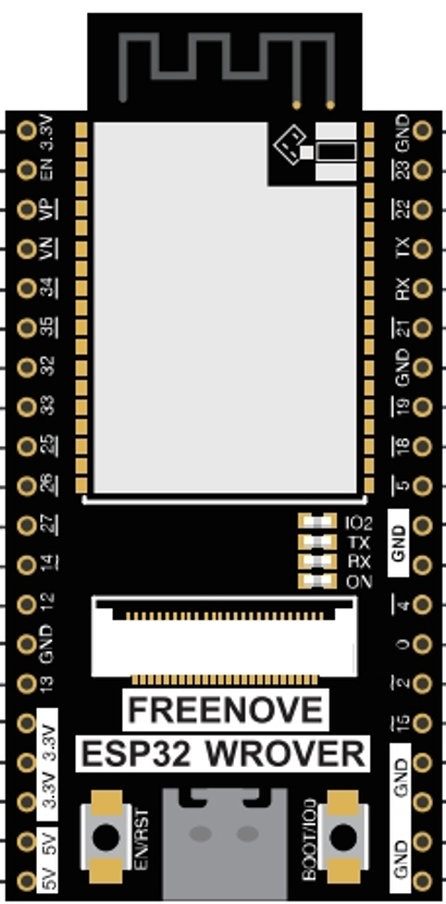
Pin Configuration and Descriptions
The FREENOVE ESP32 WROVER has a total of 36 GPIO pins, each with specific functions. Below is a summary of the pin configuration:
| Pin | Function | Description |
|---|---|---|
| VIN | Power Input | Accepts 3.3V input for powering the board. |
| GND | Ground | Common ground for the circuit. |
| GPIO0 | General Purpose I/O, Boot Mode | Used for boot mode selection and general-purpose input/output. |
| GPIO2 | General Purpose I/O, ADC, PWM | Can be used for analog input, PWM, or digital I/O. |
| GPIO4 | General Purpose I/O, ADC, PWM | Supports analog input, PWM, or digital I/O. |
| GPIO12 | General Purpose I/O, ADC, PWM | Multi-function pin for analog input, PWM, or digital I/O. |
| GPIO13 | General Purpose I/O, ADC, PWM | Multi-function pin for analog input, PWM, or digital I/O. |
| GPIO21 | I2C SDA | Data line for I2C communication. |
| GPIO22 | I2C SCL | Clock line for I2C communication. |
| GPIO23 | SPI MOSI | Master Out Slave In for SPI communication. |
| GPIO18 | SPI SCK | Clock line for SPI communication. |
| GPIO19 | SPI MISO | Master In Slave Out for SPI communication. |
| GPIO16 | UART RX | Receive pin for UART communication. |
| GPIO17 | UART TX | Transmit pin for UART communication. |
Note: Some GPIO pins have specific restrictions or are reserved for internal functions. Refer to the official datasheet for detailed pin mappings.
Usage Instructions
How to Use the Component in a Circuit
Powering the Board:
- Connect the board to a 5V USB power source or supply 3.3V to the VIN pin.
- Ensure the power source can provide sufficient current (at least 500 mA).
Programming the Board:
- Use the Arduino IDE or Espressif's ESP-IDF (IoT Development Framework) to program the board.
- Install the necessary drivers and libraries for ESP32 in your development environment.
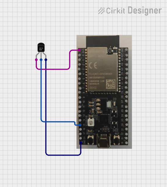
Connecting Peripherals:
- Use the GPIO pins to connect sensors, actuators, or other devices.
- Ensure the voltage levels of connected devices are compatible with the 3.3V logic of the ESP32.
Wireless Communication:
- Configure the Wi-Fi and Bluetooth settings in your code to enable wireless communication.
- Use the built-in libraries for seamless integration.
Important Considerations and Best Practices
- Voltage Levels: Avoid applying voltages higher than 3.3V to the GPIO pins to prevent damage.
- Deep Sleep Mode: Use deep sleep mode to conserve power in battery-powered applications.
- Pin Multiplexing: Some pins have multiple functions. Check the datasheet to avoid conflicts.
- Antenna Placement: Ensure the onboard antenna has sufficient clearance for optimal wireless performance.
Example Code for Arduino UNO Integration
Below is an example of how to use the FREENOVE ESP32 WROVER with the Arduino IDE to connect to a Wi-Fi network:
#include <WiFi.h> // Include the Wi-Fi library for ESP32

// Replace with your network credentials
const char* ssid = "Your_SSID";
const char* password = "Your_PASSWORD";

void setup() {
  Serial.begin(115200); // Initialize serial communication at 115200 baud
  delay(1000); // Wait for a second to stabilize

  Serial.println("Connecting to Wi-Fi...");
  WiFi.begin(ssid, password); // Start Wi-Fi connection

  while (WiFi.status() != WL_CONNECTED) {
    delay(500); // Wait for connection
    Serial.print(".");
  }

  Serial.println("\nWi-Fi connected!");
  Serial.print("IP Address: ");
  Serial.println(WiFi.localIP()); // Print the assigned IP address
}

void loop() {
  // Add your main code here
}
Tip: Replace
Your_SSIDandYour_PASSWORDwith your Wi-Fi network credentials.
Troubleshooting and FAQs
Common Issues Users Might Face
Board Not Detected by Computer:
- Ensure the USB cable is functional and supports data transfer.
- Install the correct USB-to-serial driver for the ESP32.
Wi-Fi Connection Fails:
- Double-check the SSID and password in your code.
- Ensure the Wi-Fi network is within range and not using unsupported security protocols.
GPIO Pin Malfunction:
- Verify that the pin is not being used for another function (e.g., boot mode).
- Check for short circuits or incorrect wiring.
Program Upload Fails:
- Press and hold the BOOT button while uploading the code.
- Ensure the correct board and port are selected in the Arduino IDE.
Solutions and Tips for Troubleshooting
- Reset the Board: Press the RESET button to restart the microcontroller.
- Check Power Supply: Ensure the board is receiving sufficient power.
- Consult the Datasheet: Refer to the official ESP32 WROVER datasheet for advanced debugging.
- Update Libraries: Ensure you are using the latest version of the ESP32 libraries in your IDE.
By following this documentation, you can effectively utilize the FREENOVE ESP32 WROVER for a wide range of applications.