How to Use Mini 360 Buck Converter: Examples, Pinouts, and Specs
Introduction
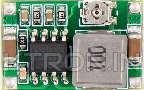
The Mini 360 Buck Converter is a compact, high-efficiency, step-down voltage regulator that converts a higher input voltage to a lower output voltage. It is based on the MP2307DN integrated circuit and is widely used in battery-powered devices, DIY electronics projects, and any application where voltage regulation is necessary to protect sensitive electronics.
Explore Projects Built with Mini 360 Buck Converter


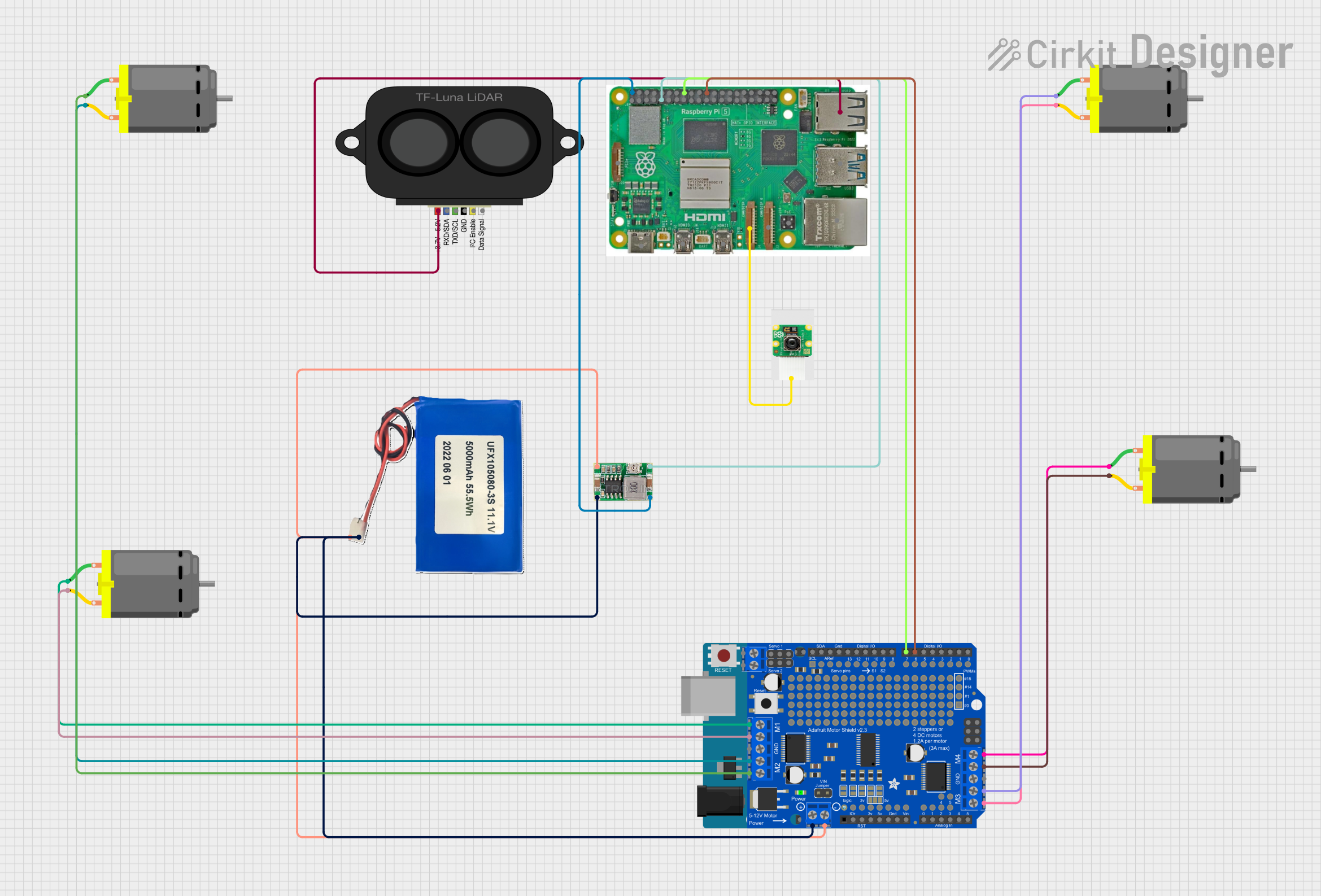
Explore Projects Built with Mini 360 Buck Converter
Common Applications and Use Cases
- Power supply for electronic devices
- Battery-powered projects
- Portable chargers
- LED drivers
- Raspberry Pi, Arduino, and other microcontroller power regulation
Technical Specifications
Key Technical Details
- Input Voltage: 4.75V to 23V
- Output Voltage: 1.0V to 17V (Adjustable via potentiometer)
- Output Current: Up to 3A (2A recommended for heat dissipation)
- Switching Frequency: 340kHz
- Efficiency: Up to 96%
- Operating Temperature: -40°C to +85°C
Pin Configuration and Descriptions
| Pin Number | Name | Description |
|---|---|---|
| 1 | VIN | Input voltage (4.75V to 23V) |
| 2 | GND | Ground connection |
| 3 | VOUT | Regulated output voltage (1.0V to 17V) |
| 4 | EN | Enable pin (pull to ground to disable) |
Usage Instructions
How to Use the Component in a Circuit
- Connect the input voltage (4.75V to 23V) to the VIN pin.
- Connect the ground from your power source to the GND pin.
- Adjust the potentiometer to achieve the desired output voltage before connecting your load.
- Connect your load to the VOUT and GND pins.
- Optionally, use the EN pin to enable or disable the converter (connect to ground to disable).
Important Considerations and Best Practices
- Always verify the output voltage with a multimeter before connecting sensitive electronics.
- Do not exceed the maximum input voltage of 23V to prevent damage.
- Ensure adequate ventilation or add a heatsink if drawing currents close to the maximum rating.
- Keep input and output wires as short as possible to minimize losses and interference.
- Use capacitors at the input and output if your application is sensitive to voltage spikes.
Troubleshooting and FAQs
Common Issues Users Might Face
- Output voltage is too high or too low: Adjust the potentiometer carefully to fine-tune the output voltage.
- Converter is overheating: Reduce the load current, improve ventilation, or add a heatsink.
- No output voltage: Check connections, input voltage, and ensure the EN pin is not pulled to ground.
Solutions and Tips for Troubleshooting
- If the output voltage does not adjust, ensure the potentiometer is functioning and not damaged.
- In case of noise-sensitive applications, add filtering capacitors to the input and output.
- If the device is not turning on, check the solder joints and components for any signs of damage.
FAQs
Q: Can I use the Mini 360 Buck Converter to charge batteries?
- A: Yes, but ensure the output voltage is appropriate for the battery and that current limits are observed.
Q: What is the purpose of the EN pin?
- A: The EN (enable) pin is used to turn the converter on or off. Pulling it to ground will disable the output.
Q: How do I set the output voltage?
- A: Turn the potentiometer clockwise to increase and counterclockwise to decrease the output voltage.
Example Code for Arduino UNO
Below is an example code snippet for reading the output voltage of the Mini 360 Buck Converter using an Arduino UNO. This assumes you have connected the VOUT of the converter to an analog input (A0) on the Arduino.
const int analogPin = A0; // Connect VOUT to A0

void setup() {
  Serial.begin(9600);
}

void loop() {
  int sensorValue = analogRead(analogPin);
  float voltage = sensorValue * (5.0 / 1023.0); // Convert to voltage
  Serial.print("Output Voltage: ");
  Serial.println(voltage);
  delay(1000); // Wait for a second
}
Note: This code assumes a direct connection and does not account for voltage dividers that may be necessary for higher voltages. Always use a voltage divider when the expected voltage exceeds the microcontroller's maximum analog input voltage (5V for Arduino UNO).