How to Use FLYSKY FS- IA6: Examples, Pinouts, and Specs
Introduction
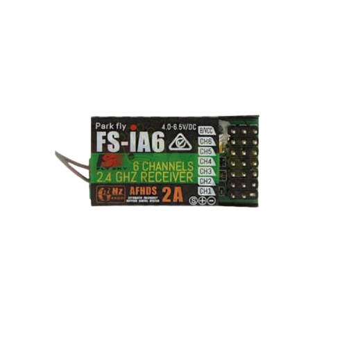
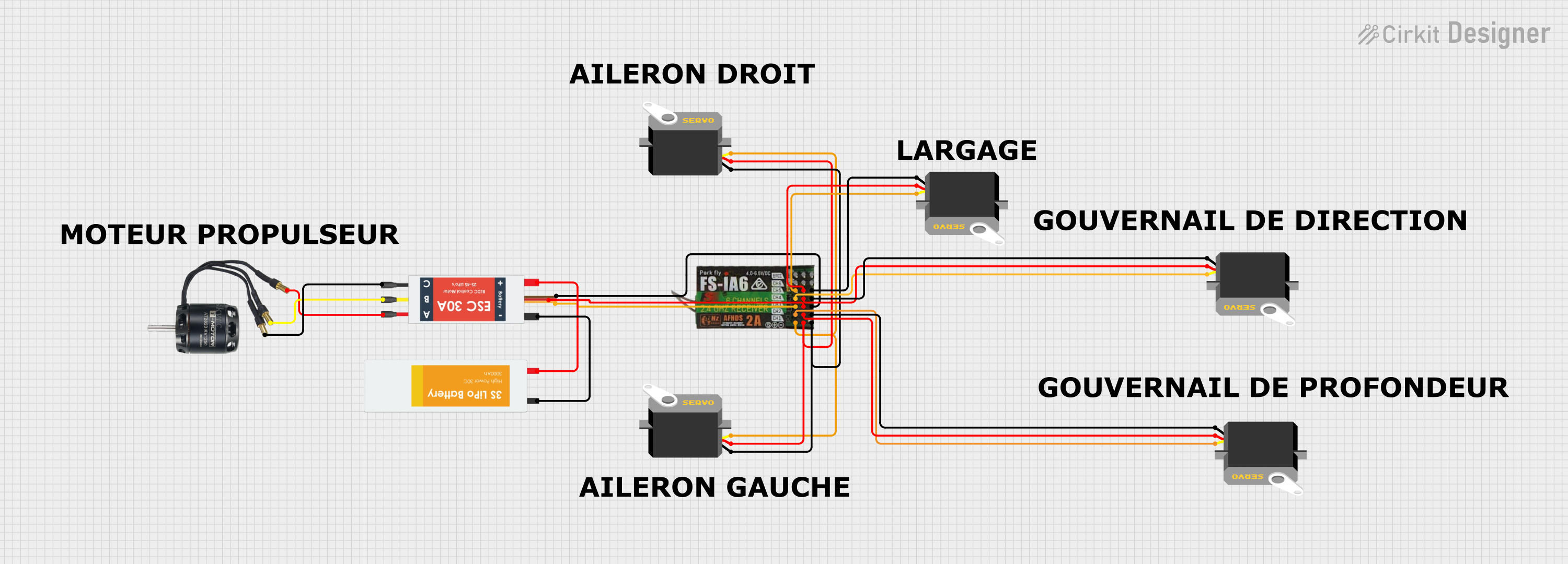
The FLYSKY FS-IA6 is a 6-channel 2.4GHz receiver designed for use with FLYSKY's range of radio transmitters. This receiver is widely used in the hobbyist community for radio-controlled (RC) vehicles, including cars, boats, and drones. Its popularity stems from its reliability, ease of use, and compatibility with a wide range of FLYSKY transmitters.
Explore Projects Built with FLYSKY FS- IA6
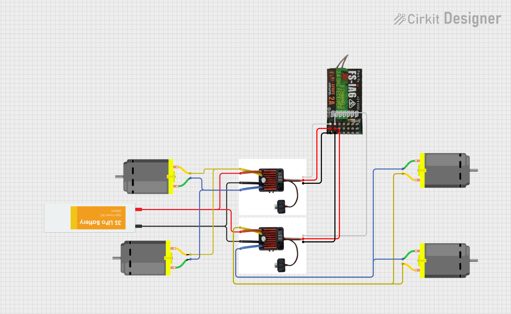
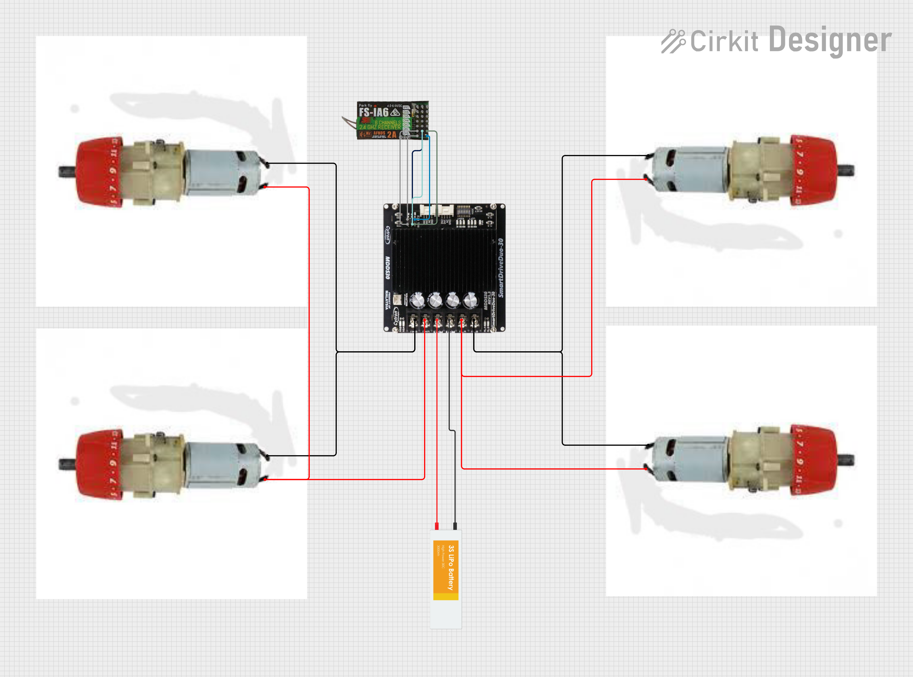
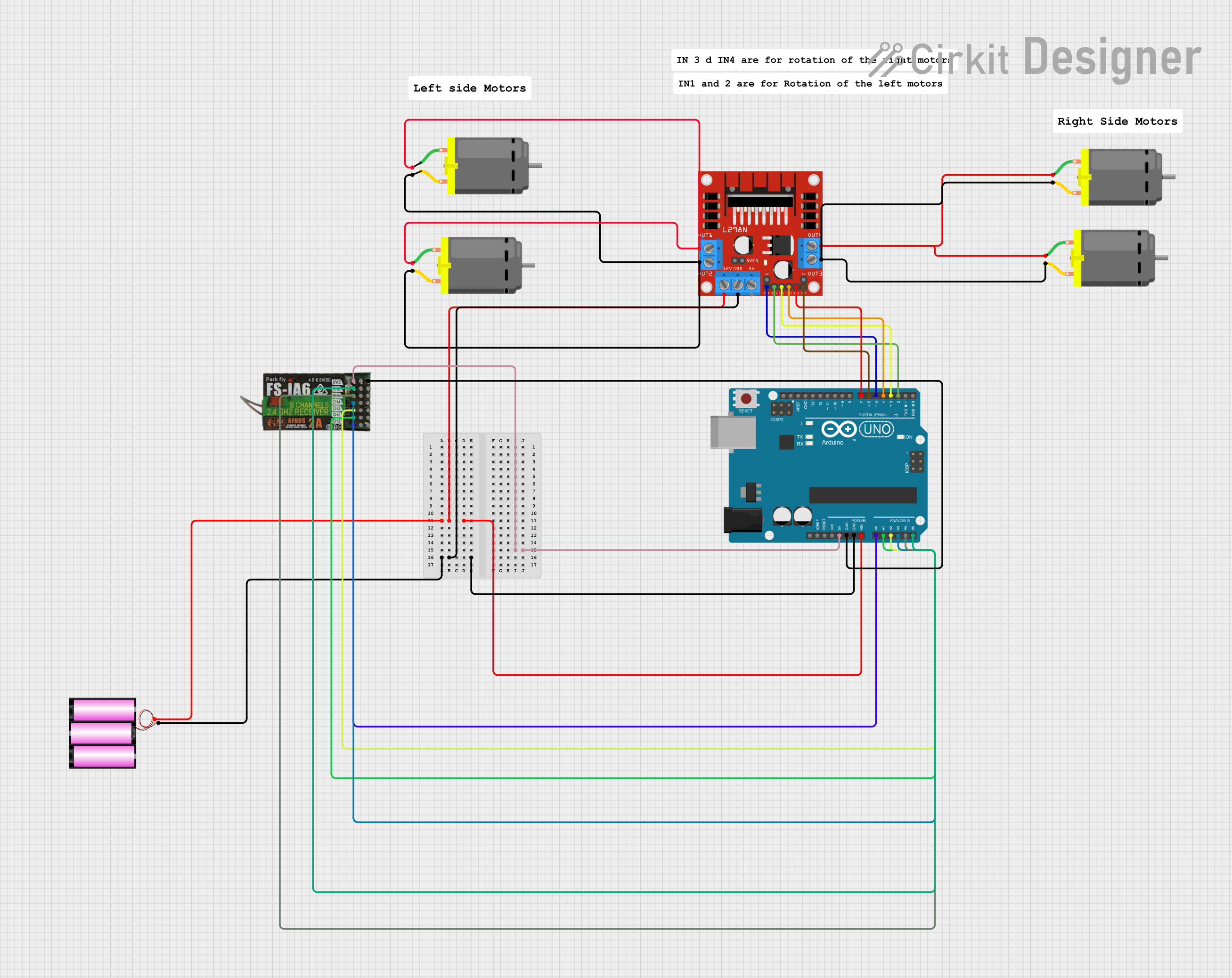
Explore Projects Built with FLYSKY FS- IA6
Common Applications and Use Cases
- RC Cars
- RC Boats
- RC Airplanes
- Drones and Quadcopters
- DIY Electronics Projects involving remote control
Technical Specifications
Key Technical Details
| Specification | Value |
|---|---|
| Frequency | 2.4GHz |
| Channels | 6 |
| Modulation Type | GFSK |
| Sensitivity | -105dBm |
| Power Input | 4.0-6.5V DC |
| Antenna Length | 26mm (Dual Antenna) |
| Dimensions | 40.421.17.35mm |
| Weight | 6.4g |
Pin Configuration and Descriptions
| Pin Number | Description |
|---|---|
| 1 | Channel 1 Output |
| 2 | Channel 2 Output |
| 3 | Channel 3 Output |
| 4 | Channel 4 Output |
| 5 | Channel 5 Output |
| 6 | Channel 6 Output |
| B/VCC | Battery Input/Power |
| GND | Ground |
Usage Instructions
How to Use the Component in a Circuit
Power Connection: Connect the positive lead of your power source to the B/VCC pin and the negative lead to the GND pin. Ensure that the power source is within the specified voltage range (4.0-6.5V DC).
Binding to Transmitter: Before use, the FS-IA6 must be bound to a compatible FLYSKY transmitter. This is typically done by pressing the bind button on the receiver while powering it on, and following the binding procedure as per the transmitter's manual.
Channel Outputs: Connect the output pins (1-6) to the corresponding servos or electronic speed controllers (ESCs) of your RC vehicle or project. Ensure that the connections are secure and that the polarity is correct.
Important Considerations and Best Practices
- Always ensure that the antenna is properly installed and not obstructed to maintain a strong signal.
- Avoid placing the receiver near metal objects or electronic interference sources.
- Check and double-check all connections before powering up to prevent damage.
- Use a regulated power supply to avoid voltage spikes that could damage the receiver.
Troubleshooting and FAQs
Common Issues
- Signal Loss: Ensure that the antennas are properly installed and not damaged. Check for potential sources of interference.
- Binding Failure: Make sure the receiver is in binding mode and that the transmitter is compatible and in close proximity during the binding process.
- Unresponsive Channels: Verify that the servos/ESCs are properly connected and functioning. Check the transmitter settings to ensure the correct channels are active.
Solutions and Tips for Troubleshooting
- Rebinding: If the receiver is not responding correctly, try rebinding it to the transmitter.
- Power Cycle: In case of erratic behavior, power cycle the receiver by disconnecting and reconnecting the power source.
- Firmware Update: Ensure that both the receiver and transmitter are running the latest firmware available from FLYSKY.
FAQs
Q: Can I use the FS-IA6 with a transmitter from another brand? A: The FS-IA6 is designed to work with FLYSKY transmitters. Compatibility with other brands is not guaranteed.
Q: How do I know if the receiver is receiving a signal? A: The receiver has an LED indicator that shows its operational status. A solid light typically indicates a good connection.
Q: What should I do if one of the channels is not working? A: Check the connection to the channel, ensure the servo/ESC is functioning, and verify the channel mapping in the transmitter.
Example Code for Arduino UNO
The following is an example of how to read PWM signals from the FS-IA6 receiver using an Arduino UNO. This code reads the value of channel 1 and prints it to the serial monitor.
#include <Servo.h>

Servo myServo;  // Create servo object to control a servo

void setup() {
  myServo.attach(9);  // Attaches the servo on pin 9 to the servo object
  Serial.begin(9600); // Starts serial communication at 9600 baud
}

void loop() {
  int pulseWidth;

  // Read the pulse width of the first channel
  pulseWidth = pulseIn(2, HIGH); // Assumes channel 1 is connected to pin 2

  // Print the pulse width to the serial monitor
  Serial.println(pulseWidth);

  // Control the servo with the pulse width value
  myServo.writeMicroseconds(pulseWidth);

  delay(10); // Delay a little bit to improve stability
}
Note: The pulseIn function is used to measure the width of a pulse (HIGH or LOW) on a pin. In this case, it's used to read the PWM signal from the receiver.
Remember to adjust the pin numbers and the code logic according to your specific application and the channels you are using.