How to Use SMD MOSFET: Examples, Pinouts, and Specs
Introduction
The SMD MOSFET (Surface-Mount Device Metal-Oxide-Semiconductor Field-Effect Transistor) is a compact, high-performance electronic component designed for switching and amplifying electronic signals. Its surface-mount design makes it ideal for applications where space is limited, such as in modern consumer electronics, automotive systems, and industrial equipment.
This component is widely used in power management circuits, motor drivers, LED drivers, and signal processing applications due to its efficiency, fast switching speed, and low power loss.
Explore Projects Built with SMD MOSFET


Explore Projects Built with SMD MOSFET
Common Applications:
- Power supply circuits
- Motor control and drivers
- LED lighting systems
- Signal amplification
- Battery management systems
- High-frequency switching circuits
Technical Specifications
Below are the key technical details for the Generic SMD MOSFET:
| Parameter | Value |
|---|---|
| Manufacturer Part ID | SMD MOSFET |
| Type | N-Channel or P-Channel |
| Maximum Drain-Source Voltage (VDS) | 20V to 100V (varies by model) |
| Maximum Gate-Source Voltage (VGS) | ±20V |
| Continuous Drain Current (ID) | 1A to 30A (varies by model) |
| Power Dissipation (PD) | 1W to 50W (varies by model) |
| RDS(on) (On-Resistance) | 0.01Ω to 0.1Ω (typical) |
| Package Type | SOT-23, SOIC, or DFN |
| Operating Temperature | -55°C to +150°C |
Pin Configuration
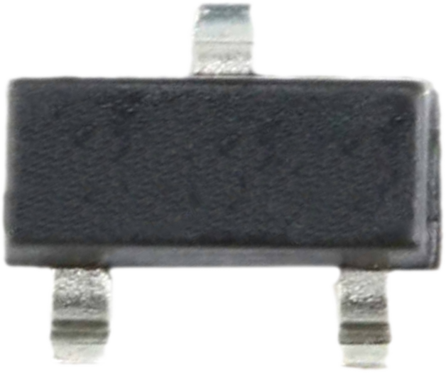
The pin configuration of the SMD MOSFET depends on the specific package type. Below is an example for the SOT-23 package:
| Pin Number | Pin Name | Description |
|---|---|---|
| 1 | Gate (G) | Controls the MOSFET switching |
| 2 | Drain (D) | Current flows into this terminal |
| 3 | Source (S) | Current flows out of this terminal |
For other package types (e.g., SOIC or DFN), refer to the specific datasheet for pinout details.
Usage Instructions
How to Use the SMD MOSFET in a Circuit
- Determine the Type: Identify whether the MOSFET is N-Channel or P-Channel. N-Channel MOSFETs are typically used for low-side switching, while P-Channel MOSFETs are used for high-side switching.
- Connect the Pins:
- Gate (G): Connect to the control signal (e.g., from a microcontroller or driver circuit).
- Drain (D): Connect to the load (e.g., motor, LED, or other devices).
- Source (S): Connect to the ground (N-Channel) or power supply (P-Channel).
- Gate Resistor: Use a resistor (typically 10Ω to 100Ω) between the control signal and the Gate to limit inrush current and prevent oscillations.
- Flyback Diode: For inductive loads (e.g., motors or relays), add a flyback diode across the load to protect the MOSFET from voltage spikes.
- Heat Dissipation: Ensure proper heat dissipation using a heatsink or PCB thermal vias if the MOSFET operates at high power levels.
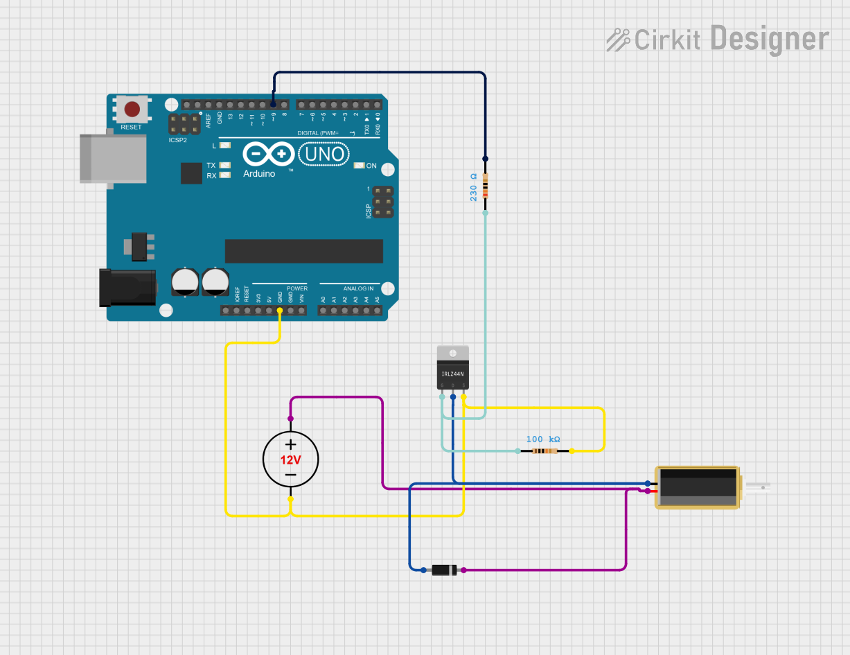
Example Circuit with Arduino UNO
Below is an example of using an N-Channel SMD MOSFET to control an LED with an Arduino UNO:
// Define the MOSFET Gate pin connected to Arduino
const int mosfetGatePin = 9; // Pin 9 controls the MOSFET Gate

void setup() {
  pinMode(mosfetGatePin, OUTPUT); // Set the Gate pin as an output
}

void loop() {
  digitalWrite(mosfetGatePin, HIGH); // Turn on the MOSFET (LED ON)
  delay(1000); // Wait for 1 second
  digitalWrite(mosfetGatePin, LOW);  // Turn off the MOSFET (LED OFF)
  delay(1000); // Wait for 1 second
}
Important Considerations:
- Voltage Levels: Ensure the Gate-Source voltage (VGS) is within the specified range to avoid damaging the MOSFET.
- Current Handling: Verify that the MOSFET can handle the load current without exceeding its maximum ratings.
- Static Sensitivity: MOSFETs are sensitive to static electricity. Use proper ESD precautions during handling and assembly.
Troubleshooting and FAQs
Common Issues and Solutions
MOSFET Overheating:
- Cause: Exceeding the maximum current or power dissipation rating.
- Solution: Use a heatsink or improve PCB thermal management. Ensure the MOSFET is rated for the load current.
MOSFET Not Switching:
- Cause: Insufficient Gate voltage or incorrect wiring.
- Solution: Verify the Gate-Source voltage (VGS) and ensure proper connections.
Load Not Turning Off Completely:
- Cause: High RDS(on) or insufficient Gate drive voltage.
- Solution: Use a MOSFET with lower RDS(on) or increase the Gate drive voltage.
MOSFET Damaged During Operation:
- Cause: Voltage spikes from inductive loads or ESD damage.
- Solution: Add a flyback diode for inductive loads and handle the MOSFET with proper ESD precautions.
FAQs
Q1: Can I use an SMD MOSFET for high-power applications?
A1: Yes, but ensure the MOSFET's power dissipation and current ratings are sufficient. Use proper heat management techniques.
Q2: How do I choose between N-Channel and P-Channel MOSFETs?
A2: Use N-Channel MOSFETs for low-side switching (load connected to the Drain) and P-Channel MOSFETs for high-side switching (load connected to the Source).
Q3: Can I drive an SMD MOSFET directly from an Arduino?
A3: Yes, but ensure the MOSFET's Gate threshold voltage (VGS(th)) is compatible with the Arduino's output voltage (typically 5V or 3.3V).
Q4: What is the advantage of using an SMD MOSFET over a through-hole MOSFET?
A4: SMD MOSFETs are more compact, making them ideal for space-constrained designs. They also offer better thermal performance when mounted on a properly designed PCB.
By following this documentation, you can effectively integrate the Generic SMD MOSFET into your electronic designs for efficient switching and amplification.