How to Use 125 A DC breaker: Examples, Pinouts, and Specs
Introduction
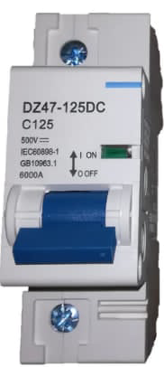
The 125 A DC breaker is a high-capacity direct current circuit breaker designed to protect electrical circuits from overloads and short circuits. It ensures safe operation in DC applications by interrupting the current flow when abnormal conditions are detected. This breaker is commonly used in renewable energy systems, electric vehicles, industrial machinery, and battery storage systems.
Explore Projects Built with 125 A DC breaker

Explore Projects Built with 125 A DC breaker
Common Applications and Use Cases
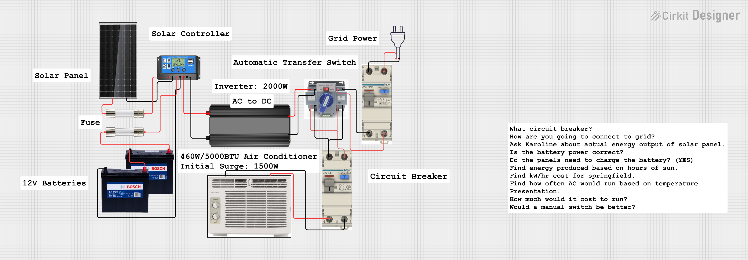
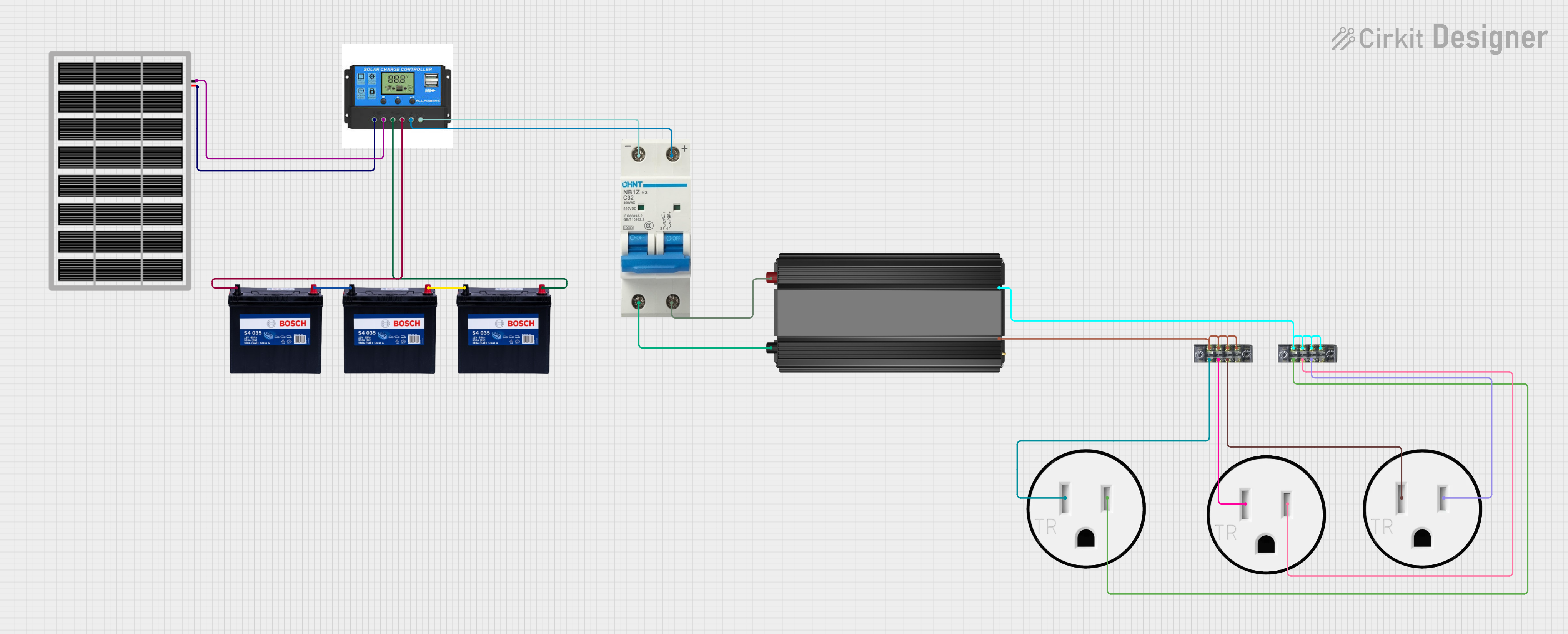
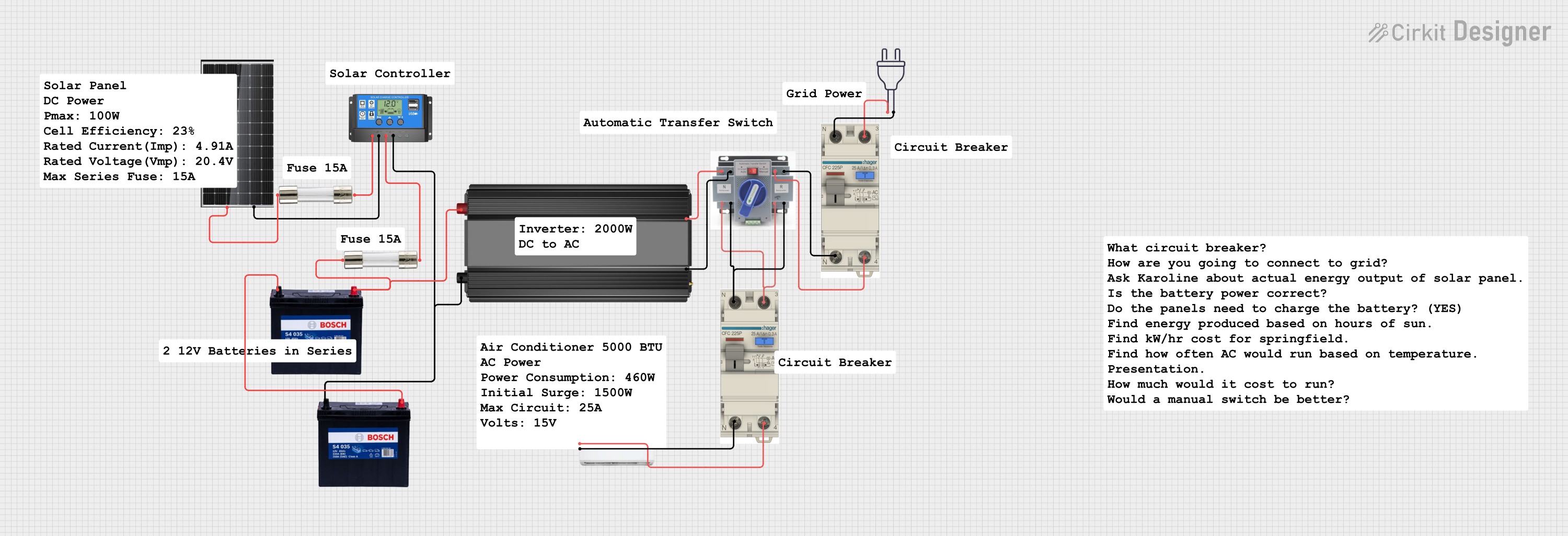
- Solar Power Systems: Protects photovoltaic (PV) arrays and inverters from overcurrent conditions.
- Electric Vehicles (EVs): Safeguards battery packs and motor controllers.
- Battery Energy Storage Systems (BESS): Prevents damage to batteries and associated electronics.
- Industrial DC Equipment: Ensures safe operation of heavy-duty DC machinery.
- Marine Applications: Protects DC circuits in boats and yachts.
Technical Specifications
The following table outlines the key technical details of the 125 A DC breaker:
| Parameter | Value |
|---|---|
| Rated Current | 125 A |
| Rated Voltage | Up to 500 V DC |
| Breaking Capacity | 10 kA |
| Number of Poles | 1P, 2P, or 3P (varies by model) |
| Operating Temperature | -25°C to +70°C |
| Mounting Type | DIN rail or panel-mounted |
| Trip Mechanism | Thermal-magnetic |
| Compliance Standards | IEC 60947-2, UL 1077 |
Pin Configuration and Descriptions
The 125 A DC breaker typically has two main terminals for input and output connections. The table below describes the terminal configuration:
| Terminal | Description |
|---|---|
| Line (L) | Connects to the positive side of the DC power source. |
| Load (OUT) | Connects to the load or downstream circuit. |
Usage Instructions
How to Use the 125 A DC Breaker in a Circuit
Determine the Circuit Requirements:
- Ensure the breaker’s rated current (125 A) and voltage (up to 500 V DC) match the circuit specifications.
- Verify that the breaking capacity (10 kA) is sufficient for the application.
Mounting the Breaker:
- Install the breaker on a DIN rail or secure it to a panel using screws, depending on the model.
- Ensure proper orientation, with the Line terminal connected to the power source.
Wiring the Breaker:
- Use appropriately rated cables for the current and voltage of the circuit.
- Connect the positive terminal of the DC power source to the Line (L) terminal.
- Connect the Load (OUT) terminal to the downstream circuit or device.
Testing the Installation:
- After wiring, test the breaker by manually toggling it on and off to ensure proper operation.
- Apply a small load to verify that the breaker trips under fault conditions.
Important Considerations and Best Practices
- Cable Sizing: Use cables with sufficient current-carrying capacity to prevent overheating.
- Polarity: Ensure correct polarity when connecting the breaker to avoid damage.
- Environmental Conditions: Avoid installing the breaker in areas with excessive moisture, dust, or vibration.
- Regular Maintenance: Periodically inspect the breaker for signs of wear, corrosion, or damage.
Example: Connecting to a Solar Charge Controller
In a solar power system, the 125 A DC breaker can be used between the solar panels and the charge controller to protect the circuit. Below is an example of how to wire the breaker:
- Connect the positive output of the solar panels to the Line (L) terminal of the breaker.
- Connect the Load (OUT) terminal of the breaker to the positive input of the charge controller.
- Ensure the negative connections are made directly between the solar panels and the charge controller.
Troubleshooting and FAQs
Common Issues and Solutions
| Issue | Possible Cause | Solution |
|---|---|---|
| Breaker trips frequently | Overcurrent or short circuit in the load | Check the load for faults or reduce the load current. |
| Breaker does not trip under fault conditions | Faulty breaker or incorrect wiring | Verify wiring and replace the breaker if necessary. |
| Overheating of the breaker | Loose connections or undersized cables | Tighten connections and use properly rated cables. |
| Difficulty in toggling the breaker | Mechanical wear or debris in the mechanism | Inspect and clean the breaker; replace if needed. |
FAQs
Can this breaker be used for AC circuits?
- No, the 125 A DC breaker is specifically designed for direct current (DC) applications. Using it in AC circuits may result in improper operation or damage.
What is the difference between thermal and magnetic tripping?
- Thermal tripping responds to prolonged overcurrent conditions, while magnetic tripping reacts instantly to short circuits.
How do I select the correct breaker for my application?
- Consider the circuit’s voltage, current, and breaking capacity requirements. Ensure the breaker’s specifications meet or exceed these values.
Can I use this breaker in outdoor installations?
- Only if the breaker is housed in a weatherproof enclosure to protect it from environmental factors.
By following this documentation, users can safely and effectively integrate the 125 A DC breaker into their electrical systems.