How to Use LoRA E22 900T30D: Examples, Pinouts, and Specs
Introduction
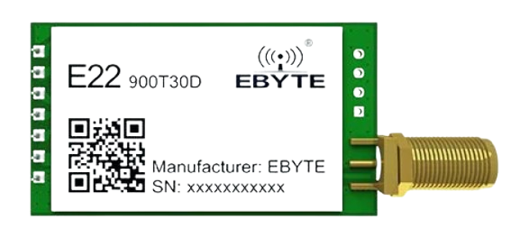
The LoRa E22 900T30D is a high-performance, long-range wireless communication module manufactured by Ebyte. It operates in the 900 MHz frequency band and is designed for low-power Internet of Things (IoT) applications. With a communication range of up to 30 kilometers (in ideal conditions) and support for various data rates, this module is ideal for applications requiring reliable, long-distance data transmission.
Explore Projects Built with LoRA E22 900T30D
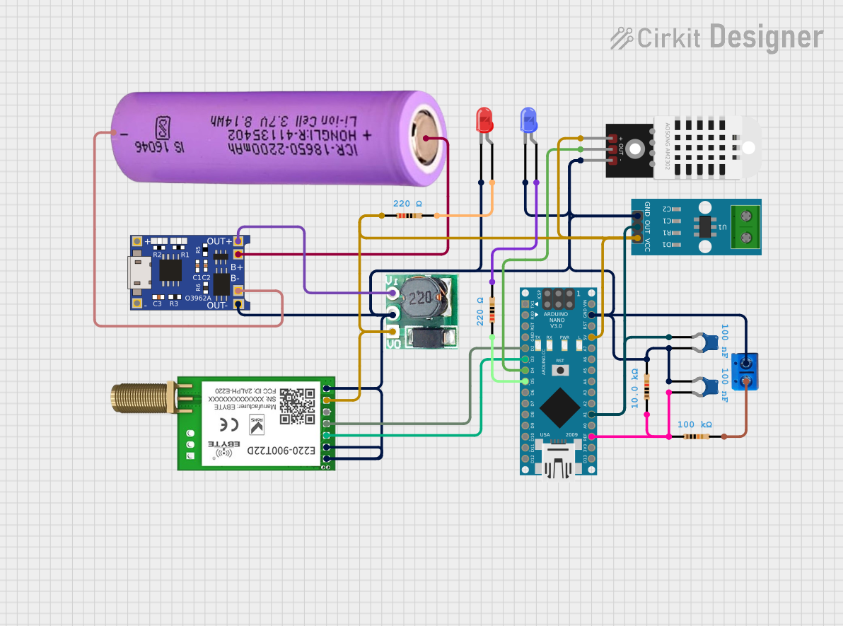


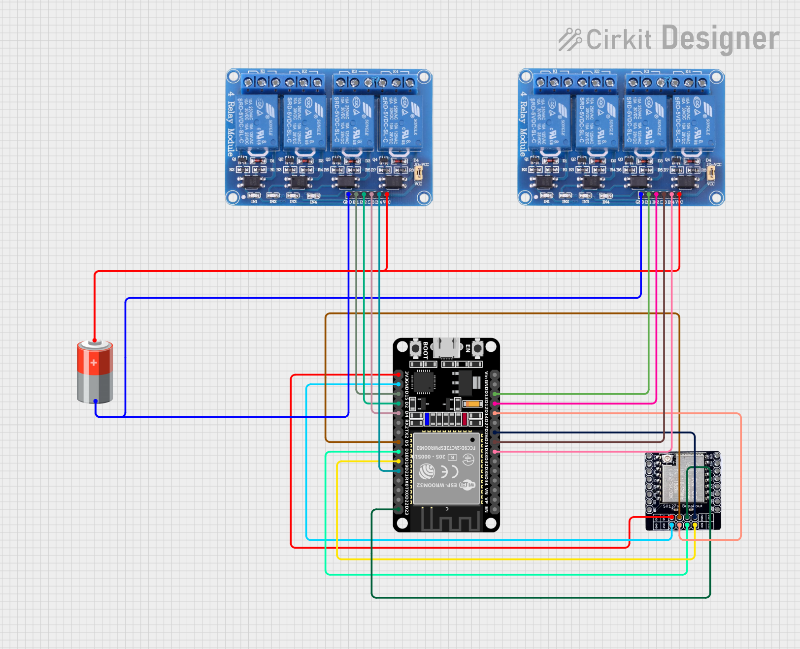
Explore Projects Built with LoRA E22 900T30D
Common Applications and Use Cases
- Smart agriculture (e.g., soil moisture monitoring, weather stations)
- Industrial automation and control systems
- Smart cities (e.g., parking sensors, streetlight control)
- Environmental monitoring (e.g., air quality sensors)
- Remote telemetry and data logging
- Wireless sensor networks
Technical Specifications
The following table outlines the key technical details of the LoRa E22 900T30D module:
| Parameter | Specification |
|---|---|
| Frequency Band | 900 MHz |
| Communication Range | Up to 30 km (line of sight) |
| Transmit Power | 30 dBm (1 W) |
| Sensitivity | -139 dBm |
| Data Rate | 0.3 kbps to 19.2 kbps |
| Operating Voltage | 3.3 V to 5.5 V |
| Current Consumption | 100 mA (transmit), 16 mA (receive) |
| Operating Temperature | -40°C to +85°C |
| Modulation Technique | LoRa (Long Range) |
| Interface | UART (TTL) |
| Dimensions | 24 mm × 43 mm × 3 mm |
Pin Configuration and Descriptions
The LoRa E22 900T30D module has 8 pins, as described in the table below:
| Pin Number | Pin Name | Description |
|---|---|---|
| 1 | M0 | Mode selection pin (connect to HIGH/LOW for different modes) |
| 2 | M1 | Mode selection pin (connect to HIGH/LOW for different modes) |
| 3 | RXD | UART receive pin (connect to TX of the microcontroller) |
| 4 | TXD | UART transmit pin (connect to RX of the microcontroller) |
| 5 | AUX | Auxiliary pin (indicates module status, e.g., busy or idle) |
| 6 | VCC | Power supply pin (3.3 V to 5.5 V) |
| 7 | GND | Ground pin |
| 8 | ANT | Antenna interface (connect to an external antenna for optimal performance) |
Usage Instructions
How to Use the Component in a Circuit
- Power Supply: Connect the VCC pin to a regulated power source (3.3 V to 5.5 V) and the GND pin to ground.
- UART Communication: Connect the RXD and TXD pins to the corresponding TX and RX pins of your microcontroller (e.g., Arduino UNO).
- Mode Selection: Use the M0 and M1 pins to configure the module's operating mode:
- Mode 0 (Normal): M0 = LOW, M1 = LOW
- Mode 1 (Wake-up): M0 = HIGH, M1 = LOW
- Mode 2 (Power-saving): M0 = LOW, M1 = HIGH
- Mode 3 (Configuration): M0 = HIGH, M1 = HIGH
- Antenna Connection: Attach an external antenna to the ANT pin for optimal signal strength and range.
- Status Monitoring: Use the AUX pin to monitor the module's status (e.g., busy or idle).
Important Considerations and Best Practices
- Use a high-quality, properly tuned antenna to achieve the maximum communication range.
- Ensure that the power supply is stable and within the specified voltage range to avoid damage to the module.
- Avoid placing the module near sources of electromagnetic interference (EMI) to maintain signal integrity.
- Configure the module's parameters (e.g., frequency, data rate) using AT commands in Configuration Mode (Mode 3).
Example: Connecting to an Arduino UNO
Below is an example of how to connect the LoRa E22 900T30D module to an Arduino UNO and send data:
Wiring Diagram
| LoRa E22 Pin | Arduino UNO Pin |
|---|---|
| VCC | 5V |
| GND | GND |
| RXD | D3 (via voltage divider if using 5V logic) |
| TXD | D2 |
| M0 | GND |
| M1 | GND |
| AUX | Not connected |
| ANT | External antenna |
Arduino Code
#include <SoftwareSerial.h>

// Define software serial pins for communication with LoRa module
SoftwareSerial LoRaSerial(2, 3); // RX = 2, TX = 3

void setup() {
  // Initialize serial communication
  Serial.begin(9600); // For debugging via Serial Monitor
  LoRaSerial.begin(9600); // Communication with LoRa module

  Serial.println("LoRa E22 900T30D Test");
  delay(1000);
}

void loop() {
  // Send data to LoRa module
  LoRaSerial.println("Hello, LoRa!");
  Serial.println("Data sent: Hello, LoRa!");

  // Wait for 1 second before sending the next message
  delay(1000);
}
Troubleshooting and FAQs
Common Issues and Solutions
No Communication Between Devices
- Ensure that the RXD and TXD pins are correctly connected to the microcontroller.
- Verify that the baud rate of the module matches the microcontroller's UART settings.
Poor Signal Strength or Range
- Check the antenna connection and ensure it is properly tuned for the 900 MHz frequency band.
- Avoid physical obstructions and sources of interference between the transmitter and receiver.
Module Not Responding to AT Commands
- Ensure the module is in Configuration Mode (M0 = HIGH, M1 = HIGH).
- Double-check the wiring and power supply connections.
High Power Consumption
- Use Power-saving Mode (M0 = LOW, M1 = HIGH) to reduce power consumption during idle periods.
FAQs
Q: Can the LoRa E22 900T30D module communicate with other LoRa modules?
A: Yes, as long as the frequency, data rate, and other communication parameters are configured to match.
Q: What is the maximum data rate supported by the module?
A: The module supports data rates up to 19.2 kbps.
Q: Can I use the module with a 5V microcontroller?
A: Yes, the module supports a 3.3 V to 5.5 V power supply. However, use a voltage divider or level shifter for the RXD pin if the microcontroller operates at 5V logic levels.
Q: How can I increase the communication range?
A: Use a high-gain antenna, ensure a clear line of sight, and reduce the data rate to improve range.