How to Use Raspberry Pi Motor Driver Board: Examples, Pinouts, and Specs
Introduction
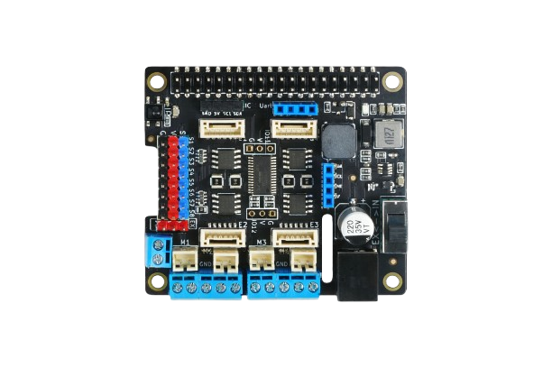
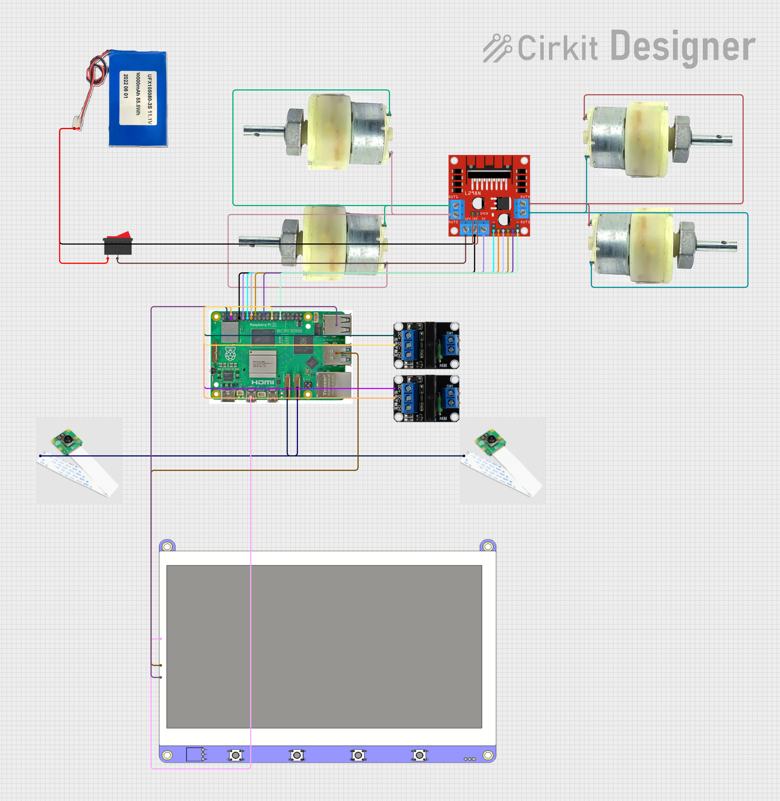
The Raspberry Pi Motor Driver Board by DFRobot (Manufacturer Part ID: Raspberry Pi) is a versatile interface board designed to enable motor control using a Raspberry Pi. It provides the necessary power and control signals to drive DC motors and stepper motors, making it an essential component for robotics and automation projects. The board features integrated H-bridge circuits, allowing for bidirectional motor control and speed regulation.
Explore Projects Built with Raspberry Pi Motor Driver Board
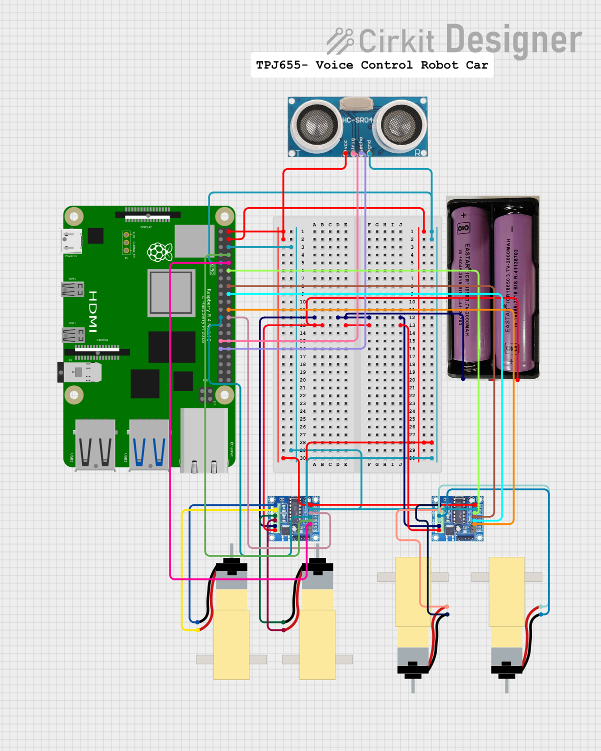
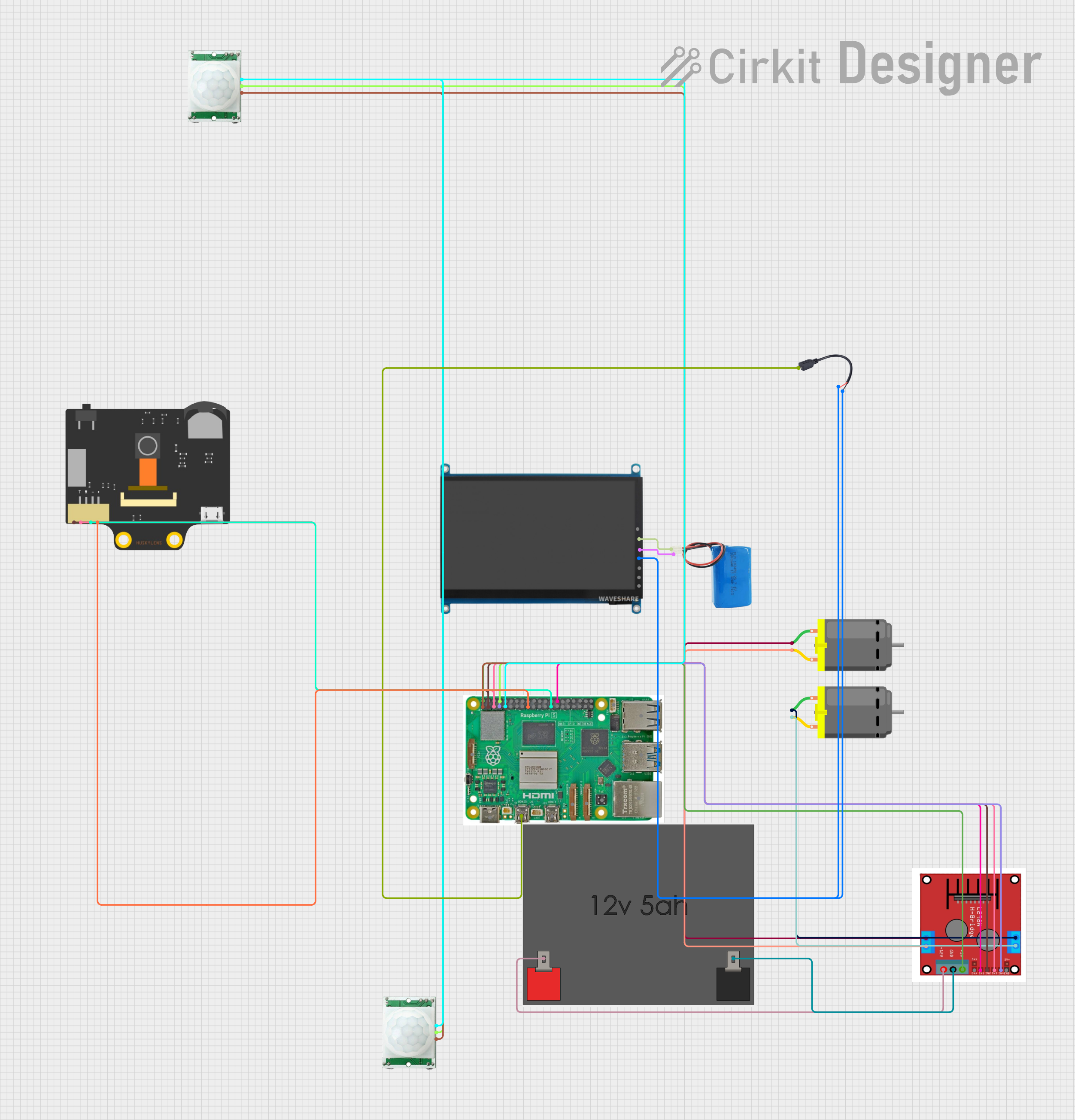
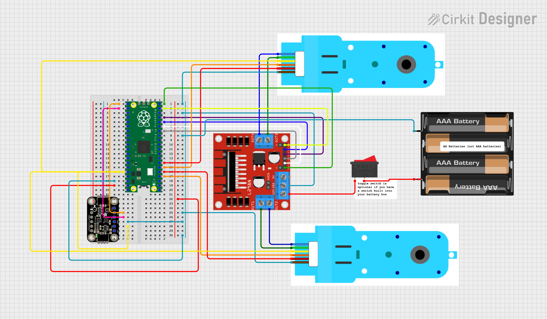
Explore Projects Built with Raspberry Pi Motor Driver Board
Common Applications and Use Cases
- Robotics: Driving wheels or robotic arms.
- Automation: Controlling conveyor belts or actuators.
- DIY Projects: Building motorized toys or custom motorized systems.
- Education: Learning about motor control and interfacing with Raspberry Pi.
Technical Specifications
Below are the key technical details of the Raspberry Pi Motor Driver Board:
| Specification | Details |
|---|---|
| Operating Voltage | 6V to 12V |
| Logic Voltage | 3.3V (compatible with Raspberry Pi GPIO) |
| Maximum Motor Current | 1.5A per channel |
| Number of Channels | 2 (supports two DC motors or one stepper motor) |
| Motor Driver IC | L298N or equivalent H-bridge driver |
| Communication Interface | GPIO pins of Raspberry Pi |
| Dimensions | 65mm x 56mm x 20mm |
| Weight | ~40g |
Pin Configuration and Descriptions
The Raspberry Pi Motor Driver Board connects to the Raspberry Pi GPIO header and provides the following pin configuration:
| Pin Name | Pin Number | Description |
|---|---|---|
| IN1 | GPIO Pin 17 | Control signal for Motor 1 (Direction 1) |
| IN2 | GPIO Pin 18 | Control signal for Motor 1 (Direction 2) |
| IN3 | GPIO Pin 22 | Control signal for Motor 2 (Direction 1) |
| IN4 | GPIO Pin 23 | Control signal for Motor 2 (Direction 2) |
| ENA | GPIO Pin 27 | PWM signal for Motor 1 (Speed control) |
| ENB | GPIO Pin 24 | PWM signal for Motor 2 (Speed control) |
| VCC | External Input | Power supply for motors (6V to 12V) |
| GND | Ground | Common ground for Raspberry Pi and motors |
Usage Instructions
How to Use the Component in a Circuit
Connect the Motor Driver Board to the Raspberry Pi:
- Align the motor driver board with the GPIO header of the Raspberry Pi and securely attach it.
- Ensure the board is powered using an external power source (6V to 12V) connected to the VCC and GND terminals.
Connect Motors:
- Attach the terminals of the DC motors or stepper motor to the motor output terminals (M1 and M2) on the board.
Write Control Code:
- Use the Raspberry Pi GPIO pins to send control signals to the motor driver board.
- Utilize PWM signals for speed control and GPIO logic levels for direction control.
Power On:
- Power on the Raspberry Pi and the motor driver board. Ensure the external power supply is sufficient for the motors.
Important Considerations and Best Practices
- Power Supply: Use a power supply that matches the voltage and current requirements of your motors.
- Heat Dissipation: The motor driver IC may heat up during operation. Use a heatsink if necessary.
- GPIO Protection: Avoid short circuits or overloading the GPIO pins of the Raspberry Pi.
- Motor Compatibility: Ensure the motors' voltage and current ratings are within the board's specifications.
Example Code for Raspberry Pi
Below is an example Python script to control a DC motor using the Raspberry Pi Motor Driver Board:
import RPi.GPIO as GPIO
import time
Pin configuration
IN1 = 17 # Motor 1 Direction 1 IN2 = 18 # Motor 1 Direction 2 ENA = 27 # Motor 1 Speed (PWM)
GPIO setup
GPIO.setmode(GPIO.BCM) GPIO.setup(IN1, GPIO.OUT) GPIO.setup(IN2, GPIO.OUT) GPIO.setup(ENA, GPIO.OUT)
Initialize PWM on ENA pin
pwm = GPIO.PWM(ENA, 100) # 100 Hz frequency pwm.start(0) # Start with 0% duty cycle (motor off)
try: # Set motor direction GPIO.output(IN1, GPIO.HIGH) # Direction 1 GPIO.output(IN2, GPIO.LOW) # Direction 2
# Gradually increase motor speed
for duty_cycle in range(0, 101, 10):  # 0% to 100% in steps of 10%
    pwm.ChangeDutyCycle(duty_cycle)
    time.sleep(0.5)  # Wait 0.5 seconds

# Stop the motor
pwm.ChangeDutyCycle(0)  # Set speed to 0%
GPIO.output(IN1, GPIO.LOW)
GPIO.output(IN2, GPIO.LOW)
finally: # Cleanup GPIO settings pwm.stop() GPIO.cleanup()
Troubleshooting and FAQs
Common Issues and Solutions
Motors Not Running:
- Cause: Insufficient power supply.
- Solution: Verify the external power supply voltage and current ratings.
Motor Running in the Wrong Direction:
- Cause: Incorrect GPIO logic levels.
- Solution: Swap the logic levels of IN1 and IN2 (or IN3 and IN4 for Motor 2).
Raspberry Pi Reboots When Motors Start:
- Cause: Voltage drop due to high motor current.
- Solution: Use a separate power supply for the motors and ensure proper grounding.
Overheating of Motor Driver IC:
- Cause: Prolonged high current operation.
- Solution: Attach a heatsink to the motor driver IC or reduce motor load.
FAQs
Can I control stepper motors with this board? Yes, the board supports stepper motors. Use both channels (M1 and M2) to control the stepper motor phases.
What is the maximum motor voltage supported? The board supports motor voltages between 6V and 12V.
Can I use this board with other microcontrollers? Yes, the board can be used with other microcontrollers, provided they output 3.3V or 5V logic signals.
Is the board compatible with all Raspberry Pi models? The board is compatible with most Raspberry Pi models that have a 40-pin GPIO header.