How to Use stm32: Examples, Pinouts, and Specs
Introduction
The STM32 is a family of microcontrollers manufactured by Bala, with the part ID "ST". These microcontrollers are based on the ARM Cortex-M architecture, offering a combination of high performance, low power consumption, and a rich set of peripherals. The STM32 family is widely used in embedded systems due to its versatility and scalability, making it suitable for applications ranging from simple IoT devices to complex industrial automation systems.
Explore Projects Built with stm32


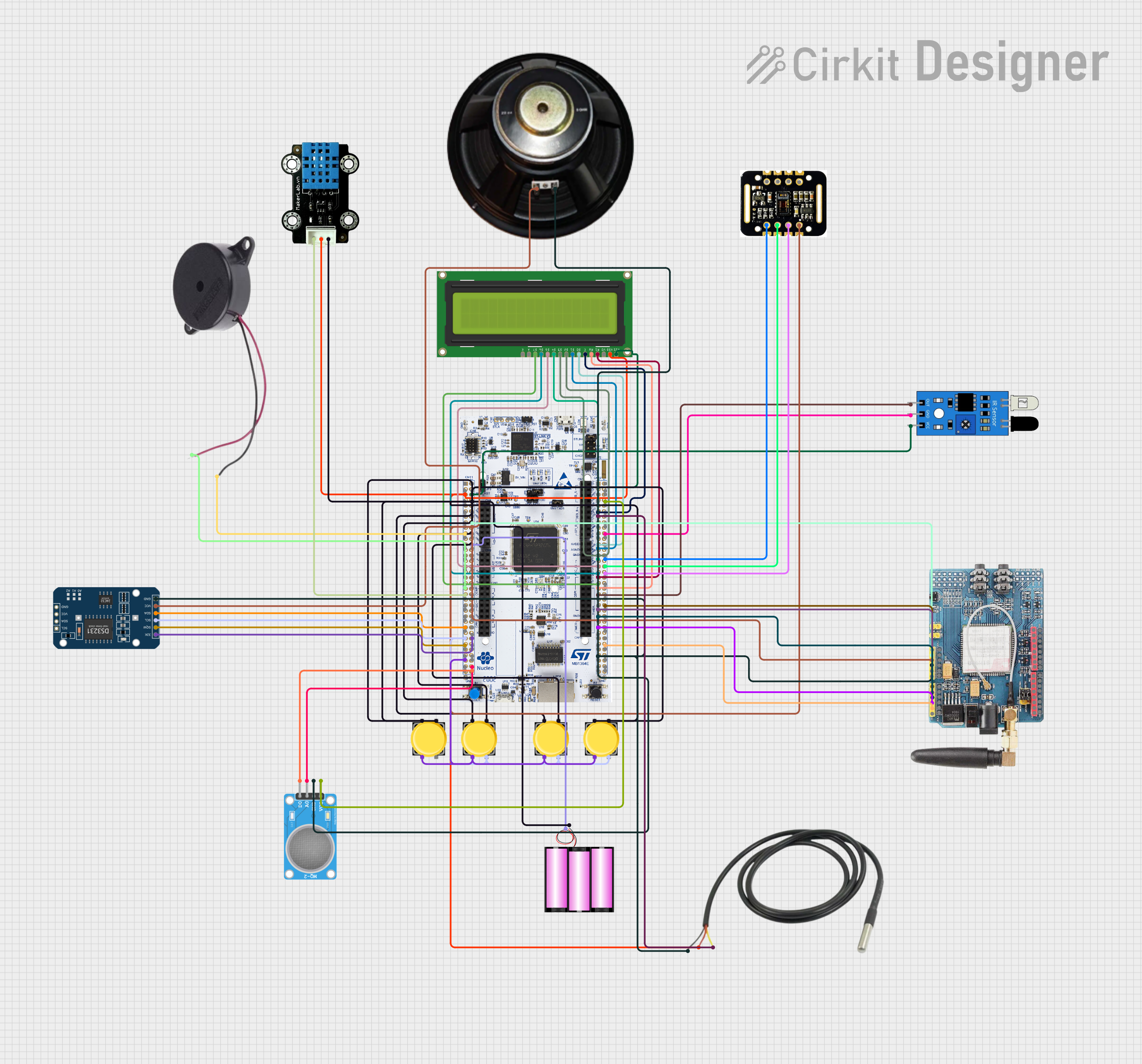
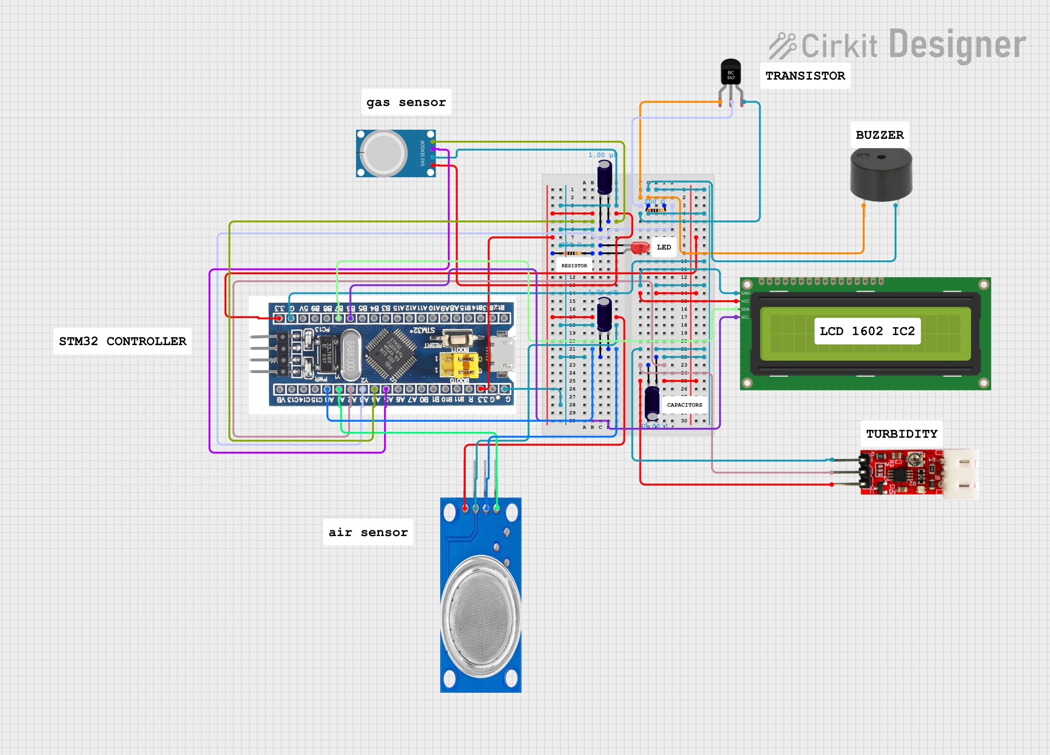
Explore Projects Built with stm32
Common Applications and Use Cases
- IoT Devices: Smart home systems, wearable devices, and connected sensors.
- Industrial Automation: Motor control, robotics, and process monitoring.
- Consumer Electronics: Audio processing, display control, and gaming peripherals.
- Medical Devices: Portable diagnostic tools and health monitoring systems.
- Automotive Systems: Engine control units, infotainment systems, and safety features.
Technical Specifications
The STM32 family includes a wide range of models, each tailored to specific performance and feature requirements. Below are the general technical specifications for the STM32 microcontrollers:
Key Technical Details
- Core: ARM Cortex-M (M0, M3, M4, or M7 depending on the model)
- Operating Voltage: 1.8V to 3.6V
- Clock Speed: Up to 480 MHz (varies by model)
- Flash Memory: 16 KB to 2 MB
- RAM: 4 KB to 1 MB
- GPIO Pins: Up to 168 (depending on the package)
- Communication Interfaces: UART, SPI, I2C, CAN, USB, Ethernet
- Timers: General-purpose, advanced, and low-power timers
- ADC/DAC: Up to 24-bit ADC and 12-bit DAC
- Power Modes: Sleep, Stop, and Standby for low-power operation
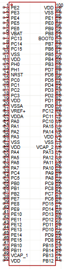
Pin Configuration and Descriptions
The pin configuration varies depending on the specific STM32 model and package. Below is an example of a typical STM32 microcontroller pinout:
| Pin Name | Function | Description |
|---|---|---|
| VDD | Power Supply | Main power supply pin (1.8V to 3.6V) |
| VSS | Ground | Ground connection |
| PA0-PA15 | GPIO/Analog | General-purpose I/O or analog input pins |
| PB0-PB15 | GPIO/Analog | General-purpose I/O or analog input pins |
| USART_TX | UART Transmit | Transmit data for UART communication |
| USART_RX | UART Receive | Receive data for UART communication |
| SPI_SCK | SPI Clock | Clock signal for SPI communication |
| SPI_MOSI | SPI Master Out Slave In | Data output for SPI communication |
| SPI_MISO | SPI Master In Slave Out | Data input for SPI communication |
| I2C_SCL | I2C Clock | Clock signal for I2C communication |
| I2C_SDA | I2C Data | Data line for I2C communication |
| ADC_IN | Analog Input | Input pin for the ADC module |
| DAC_OUT | Analog Output | Output pin for the DAC module |
| NRST | Reset | Active-low reset pin |
| BOOT0 | Boot Mode Selection | Selects boot mode (e.g., Flash, SRAM, etc.) |
Refer to the specific datasheet for your STM32 model for a complete pinout.
Usage Instructions
How to Use the STM32 in a Circuit
- Power Supply: Connect the VDD pin to a stable power source (1.8V to 3.6V) and the VSS pin to ground.
- Clock Configuration: Use an external crystal oscillator or the internal RC oscillator to provide the clock signal.
- Programming: Use an ST-Link programmer or a USB-to-serial adapter to upload firmware via the SWD or UART interface.
- Peripherals: Connect external devices (e.g., sensors, displays, or actuators) to the appropriate GPIO or communication pins.
- Boot Mode: Configure the BOOT0 pin to select the desired boot mode (e.g., Flash memory for normal operation).
Important Considerations and Best Practices
- Decoupling Capacitors: Place decoupling capacitors (e.g., 0.1 µF) close to the VDD and VSS pins to reduce noise.
- Pull-Up/Pull-Down Resistors: Use pull-up or pull-down resistors on unused pins to prevent floating states.
- ESD Protection: Add ESD protection diodes to sensitive pins for enhanced reliability.
- Debugging: Use the SWD interface for debugging and real-time monitoring of the microcontroller.
Example: Connecting STM32 to an Arduino UNO
The STM32 can communicate with an Arduino UNO via UART. Below is an example Arduino sketch for sending data to the STM32:
// Arduino UNO UART Communication with STM32
void setup() {
  Serial.begin(9600); // Initialize UART at 9600 baud rate
}

void loop() {
  Serial.println("Hello STM32!"); // Send data to STM32
  delay(1000); // Wait for 1 second
}
On the STM32 side, you can use the following code snippet to receive data:
// STM32 UART Communication Example
#include "stm32f4xx_hal.h"

UART_HandleTypeDef huart2; // UART handle for USART2

void SystemClock_Config(void);
void MX_USART2_UART_Init(void);

int main(void) {
  HAL_Init(); // Initialize the HAL library
  SystemClock_Config(); // Configure the system clock
  MX_USART2_UART_Init(); // Initialize UART

  uint8_t rxData[20]; // Buffer to store received data

  while (1) {
    HAL_UART_Receive(&huart2, rxData, sizeof(rxData), HAL_MAX_DELAY);
    // Process received data (e.g., print to debug console)
  }
}

// Note: Add the necessary HAL initialization functions and clock configuration
// based on your STM32 model and development environment.
Troubleshooting and FAQs
Common Issues and Solutions
Microcontroller Not Powering On
- Solution: Verify the power supply voltage and ensure proper connections to the VDD and VSS pins.
Unable to Program the STM32
- Solution: Check the BOOT0 pin configuration and ensure the programmer is properly connected.
Communication Issues with Peripherals
- Solution: Verify the pin connections and ensure the correct communication protocol settings (e.g., baud rate, clock speed).
Excessive Power Consumption
- Solution: Use low-power modes (e.g., Sleep or Stop) and disable unused peripherals.
FAQs
Q: Can I use the STM32 with 5V logic devices?
- A: Yes, but you will need level shifters or voltage dividers to interface 5V logic with the STM32's 3.3V GPIO.
Q: How do I select the right STM32 model for my project?
- A: Consider factors such as required performance, memory size, peripherals, and power consumption.
Q: Can I program the STM32 using the Arduino IDE?
- A: Yes, with the STM32duino core, you can program STM32 microcontrollers using the Arduino IDE.
For further details, refer to the official datasheet and reference manual for your specific STM32 model.