How to Use ESP32: Examples, Pinouts, and Specs
Introduction
The ESP32 is a low-cost, low-power system on a chip (SoC) developed by Espressif Systems. It features integrated Wi-Fi and Bluetooth capabilities, making it an ideal choice for Internet of Things (IoT) applications, smart devices, and embedded systems. The ESP32 is highly versatile, offering dual-core processing, a wide range of GPIO pins, and support for various communication protocols.
Explore Projects Built with ESP32


Explore Projects Built with ESP32
Common Applications and Use Cases
- IoT devices (e.g., smart home systems, sensors, and actuators)
- Wearable technology
- Wireless communication hubs
- Robotics and automation
- Data logging and remote monitoring
- Prototyping and development of connected devices
Technical Specifications
The ESP32 is packed with features that make it a powerful and flexible component for a wide range of applications. Below are its key technical specifications:
Key Technical Details
- Processor: Dual-core Xtensa® 32-bit LX6 microprocessor
- Clock Speed: Up to 240 MHz
- RAM: 520 KB SRAM
- Flash Memory: Typically 4 MB (varies by module)
- Wi-Fi: 802.11 b/g/n (2.4 GHz)
- Bluetooth: v4.2 BR/EDR and BLE
- Operating Voltage: 3.0V to 3.6V
- GPIO Pins: 34 (multipurpose, including ADC, DAC, PWM, I2C, SPI, UART)
- ADC Channels: 18 (12-bit resolution)
- DAC Channels: 2 (8-bit resolution)
- Power Consumption: Ultra-low power modes available
- Operating Temperature: -40°C to +125°C
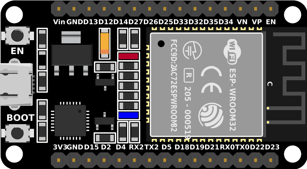
Pin Configuration and Descriptions
The ESP32 has a variety of pins for different functionalities. Below is a table summarizing the key pins and their descriptions:
| Pin Name | Function | Description |
|---|---|---|
| GPIO0 | General Purpose I/O, Boot Mode Select | Used for boot mode selection during startup. |
| GPIO2 | General Purpose I/O | Can be used as a standard GPIO pin. |
| GPIO12 | General Purpose I/O, ADC, Touch | Supports ADC and capacitive touch sensing. |
| GPIO13 | General Purpose I/O, ADC, Touch | Supports ADC and capacitive touch sensing. |
| GPIO15 | General Purpose I/O, ADC, Touch | Supports ADC and capacitive touch sensing. |
| EN | Enable | Active-high pin to enable or reset the chip. |
| 3V3 | Power Supply | Provides 3.3V power output. |
| GND | Ground | Ground connection. |
| TX0 | UART Transmit | UART0 transmit pin for serial communication. |
| RX0 | UART Receive | UART0 receive pin for serial communication. |
| ADC1_CH0 | Analog Input | First channel of ADC1 for analog-to-digital conversion. |
| DAC1 | Digital-to-Analog Converter | First DAC channel for analog signal output. |
Note: The ESP32 has multiple GPIO pins that can be configured for various functions, including PWM, I2C, SPI, and UART. Refer to the datasheet for a complete pinout.
Usage Instructions
The ESP32 can be used in a wide range of circuits and projects. Below are the steps to get started and some best practices to follow.
How to Use the ESP32 in a Circuit
- Power the ESP32: Connect the 3.3V pin to a stable 3.3V power source and GND to ground.
- Connect to a Computer: Use a USB-to-serial adapter or a development board with a built-in USB interface to connect the ESP32 to your computer.
- Install Drivers: Ensure the appropriate USB drivers for the ESP32 are installed on your computer.
- Upload Code: Use the Arduino IDE or Espressif's ESP-IDF to write and upload code to the ESP32.
- Connect Peripherals: Attach sensors, actuators, or other peripherals to the GPIO pins as needed for your project.
Important Considerations and Best Practices
- Voltage Levels: The ESP32 operates at 3.3V logic levels. Avoid connecting 5V signals directly to its GPIO pins.
- Boot Mode: Ensure GPIO0 is pulled low during startup to enter programming mode.
- Power Supply: Use a stable power source to avoid unexpected resets or malfunctions.
- Heat Management: If operating at high loads, consider adding a heatsink or ensuring proper ventilation.
Example: Connecting the ESP32 to an Arduino UNO
The ESP32 can communicate with an Arduino UNO via UART. Below is an example of how to send data from the Arduino to the ESP32:
Arduino Code
// Arduino UNO: Send data to ESP32 via UART
void setup() {
  Serial.begin(9600); // Initialize serial communication at 9600 baud
}

void loop() {
  Serial.println("Hello from Arduino!"); // Send a message to the ESP32
  delay(1000); // Wait for 1 second
}
ESP32 Code
// ESP32: Receive data from Arduino UNO via UART
void setup() {
  Serial.begin(9600); // Initialize serial communication at 9600 baud
}

void loop() {
  if (Serial.available() > 0) { // Check if data is available
    String message = Serial.readString(); // Read the incoming message
    Serial.println("Received: " + message); // Print the received message
  }
}
Tip: Ensure the TX pin of the Arduino is connected to the RX pin of the ESP32, and vice versa. Also, connect the GND of both devices.
Troubleshooting and FAQs
Common Issues and Solutions
ESP32 Not Detected by Computer
- Ensure the correct USB drivers are installed.
- Check the USB cable for damage or try a different cable.
- Verify that the ESP32 is powered correctly.
Code Upload Fails
- Ensure GPIO0 is pulled low during programming.
- Check the selected board and port in the Arduino IDE or ESP-IDF.
- Press the "BOOT" button on the ESP32 module during the upload process.
Wi-Fi Connection Issues
- Verify the SSID and password in your code.
- Ensure the Wi-Fi network is within range and not overloaded.
- Restart the ESP32 and router if necessary.
Random Resets or Instability
- Use a stable and sufficient power supply.
- Avoid excessive current draw from GPIO pins.
FAQs
Q: Can the ESP32 operate on 5V?
A: No, the ESP32 operates at 3.3V. Applying 5V to its GPIO pins can damage the chip.
Q: How do I reset the ESP32?
A: Press the "EN" button on the module to reset the ESP32.
Q: Can the ESP32 be used for Bluetooth audio?
A: Yes, the ESP32 supports Bluetooth audio streaming using the A2DP profile.
Q: How do I update the ESP32 firmware?
A: Use the Espressif Flash Download Tool or the Arduino IDE to upload new firmware.
For more detailed information, refer to the official ESP32 datasheet and technical reference manual.