How to Use LoRa SX1276: Examples, Pinouts, and Specs
Introduction
The LoRa SX1276 is a low-power, long-range transceiver designed for wireless communication in IoT (Internet of Things) applications. Manufactured by Semtech, this device operates in the sub-GHz frequency bands (137 MHz to 1020 MHz) and utilizes LoRa (Long Range) modulation technology. LoRa modulation enables extended communication range, robust data transmission, and low power consumption, making the SX1276 ideal for battery-operated devices and remote sensing applications.
Explore Projects Built with LoRa SX1276


Explore Projects Built with LoRa SX1276
Common Applications and Use Cases
- Smart agriculture (e.g., soil moisture sensors, weather stations)
- Smart cities (e.g., parking sensors, streetlight control)
- Industrial IoT (e.g., asset tracking, predictive maintenance)
- Home automation (e.g., smart meters, security systems)
- Environmental monitoring (e.g., air quality sensors, water level monitoring)
Technical Specifications
The following table outlines the key technical details of the LoRa SX1276 transceiver:
| Parameter | Value |
|---|---|
| Operating Frequency Range | 137 MHz to 1020 MHz |
| Modulation | LoRa, FSK, GFSK, MSK, GMSK, OOK |
| Sensitivity | Down to -148 dBm (LoRa mode) |
| Output Power | Up to +20 dBm (100 mW) |
| Data Rate | LoRa: 0.018 kbps to 37.5 kbps; FSK: 1.2 kbps to 300 kbps |
| Supply Voltage | 1.8 V to 3.7 V |
| Current Consumption | 10.3 mA (Rx mode), 120 mA (Tx mode at +20 dBm) |
| Operating Temperature Range | -40°C to +85°C |
| Communication Interface | SPI (Serial Peripheral Interface) |
| Package Type | QFN-28 (5 mm x 5 mm) |
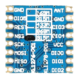
Pin Configuration and Descriptions
The SX1276 has 28 pins, and the key pin functions are described in the table below:
| Pin Number | Pin Name | Description |
|---|---|---|
| 1 | GND | Ground connection |
| 2 | RFIO | RF input/output for the antenna |
| 3 | VDD | Power supply input (1.8 V to 3.7 V) |
| 4 | DIO0 | Digital I/O pin 0 (used for interrupts and status signaling) |
| 5 | DIO1 | Digital I/O pin 1 (used for interrupts and status signaling) |
| 6 | DIO2 | Digital I/O pin 2 (used for interrupts and status signaling) |
| 7 | DIO3 | Digital I/O pin 3 (used for interrupts and status signaling) |
| 8 | DIO4 | Digital I/O pin 4 (used for interrupts and status signaling) |
| 9 | DIO5 | Digital I/O pin 5 (used for interrupts and status signaling) |
| 10 | NSS | SPI chip select (active low) |
| 11 | SCK | SPI clock input |
| 12 | MOSI | SPI master-out, slave-in |
| 13 | MISO | SPI master-in, slave-out |
| 14 | RESET | Reset pin (active low) |
| 15-28 | NC | Not connected |
Usage Instructions
How to Use the SX1276 in a Circuit
- Power Supply: Connect the VDD pin to a regulated power supply (1.8 V to 3.7 V). Ensure proper decoupling capacitors are placed close to the VDD pin to minimize noise.
- Antenna Connection: Connect the RFIO pin to an appropriate antenna for the desired frequency band. Use impedance-matching components (e.g., inductors and capacitors) to optimize performance.
- SPI Communication: Connect the SPI pins (NSS, SCK, MOSI, MISO) to the microcontroller's SPI interface. Configure the SPI clock speed according to the SX1276 datasheet.
- Digital I/O Pins: Use the DIO pins for interrupts or status signaling. These pins can be configured for various functions, such as packet reception or transmission completion.
- Reset: Connect the RESET pin to the microcontroller or an external reset circuit. Pull the pin low to reset the device.
Important Considerations and Best Practices
- Frequency Band Compliance: Ensure the operating frequency complies with local regulations (e.g., 868 MHz for Europe, 915 MHz for North America).
- Antenna Design: Use a high-quality antenna and proper impedance matching to maximize range and minimize power loss.
- Power Consumption: Use the SX1276's sleep mode to reduce power consumption in battery-operated devices.
- Firmware Configuration: Configure the LoRa parameters (e.g., spreading factor, bandwidth, coding rate) to balance range, data rate, and power consumption.
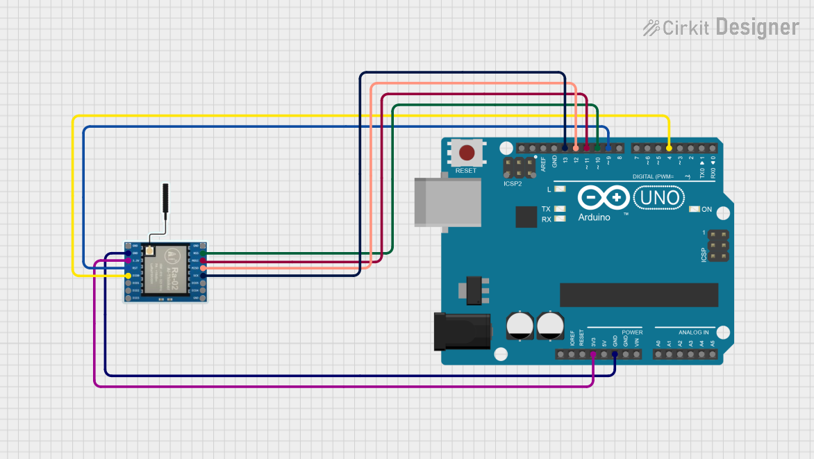
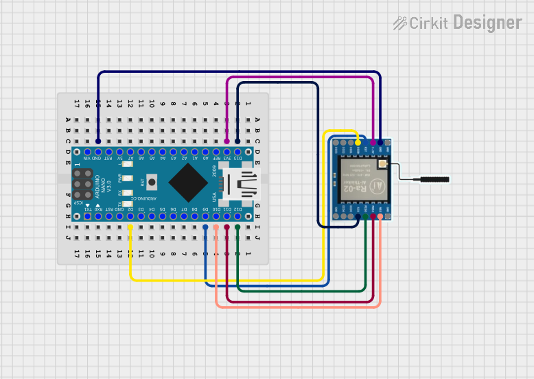
Example Code for Arduino UNO
Below is an example of how to interface the SX1276 with an Arduino UNO using the popular LoRa library:
#include <SPI.h>
#include <LoRa.h>

// Define LoRa module pins
#define NSS 10    // SPI chip select
#define RESET 9   // Reset pin
#define DIO0 2    // DIO0 pin for interrupts

void setup() {
  // Initialize serial communication for debugging
  Serial.begin(9600);
  while (!Serial);

  Serial.println("Initializing LoRa SX1276...");

  // Initialize LoRa module
  LoRa.setPins(NSS, RESET, DIO0); // Set SPI and control pins
  if (!LoRa.begin(915E6)) {       // Set frequency to 915 MHz
    Serial.println("LoRa initialization failed!");
    while (1);
  }

  Serial.println("LoRa initialized successfully!");
}

void loop() {
  // Send a test message
  Serial.println("Sending packet...");
  LoRa.beginPacket();
  LoRa.print("Hello, LoRa!");
  LoRa.endPacket();

  delay(5000); // Wait 5 seconds before sending the next packet
}
Troubleshooting and FAQs
Common Issues and Solutions
LoRa Module Not Initializing
- Cause: Incorrect wiring or SPI configuration.
- Solution: Double-check the connections between the SX1276 and the microcontroller. Ensure the SPI pins are correctly assigned in the code.
Poor Communication Range
- Cause: Improper antenna design or interference.
- Solution: Use a high-quality antenna and ensure proper impedance matching. Avoid operating near sources of RF interference.
High Power Consumption
- Cause: Device not entering sleep mode.
- Solution: Use the SX1276's low-power modes when the device is idle. Refer to the datasheet for sleep mode configuration.
Data Transmission Errors
- Cause: Incorrect LoRa parameters (e.g., spreading factor, bandwidth).
- Solution: Adjust the LoRa parameters to match the application requirements. Ensure both transmitter and receiver use the same settings.
FAQs
Q: Can the SX1276 operate in the 2.4 GHz band?
A: No, the SX1276 is designed for sub-GHz frequency bands (137 MHz to 1020 MHz).Q: What is the maximum range of the SX1276?
A: The range depends on factors such as antenna design, environment, and LoRa parameters. In ideal conditions, it can exceed 10 km.Q: Is the SX1276 compatible with other LoRa modules?
A: Yes, as long as the other modules use the same frequency band and LoRa parameters.Q: Can I use the SX1276 for FSK modulation?
A: Yes, the SX1276 supports FSK, GFSK, MSK, GMSK, and OOK modulation in addition to LoRa.
This concludes the documentation for the LoRa SX1276. For further details, refer to the official datasheet and application notes provided by Semtech.