Cirkit Designer
Your all-in-one circuit design IDE
Home /
Component Documentation
How to Use Thermocouple: Examples, Pinouts, and Specs
Introduction
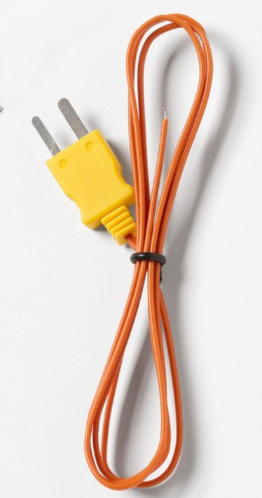
The Fluke K-Type Thermocouple is a highly reliable temperature sensor designed to measure a wide range of temperatures. It consists of two different types of metals joined at one end, which produce a voltage proportional to the temperature difference between the joined end and the other ends. This thermocouple is widely used in various industrial, scientific, and commercial applications due to its accuracy, durability, and ease of use.
Explore Projects Built with Thermocouple
PID Temperature Control System with Thermocouple and SSR

This circuit is a temperature control system that uses a thermocouple to measure temperature and a PID controller to regulate it. The PID controller drives a solid-state relay (SSR) to control an external load, with power supplied through an AC inlet socket.
Arduino UNO Based Temperature Monitoring System with OLED Display
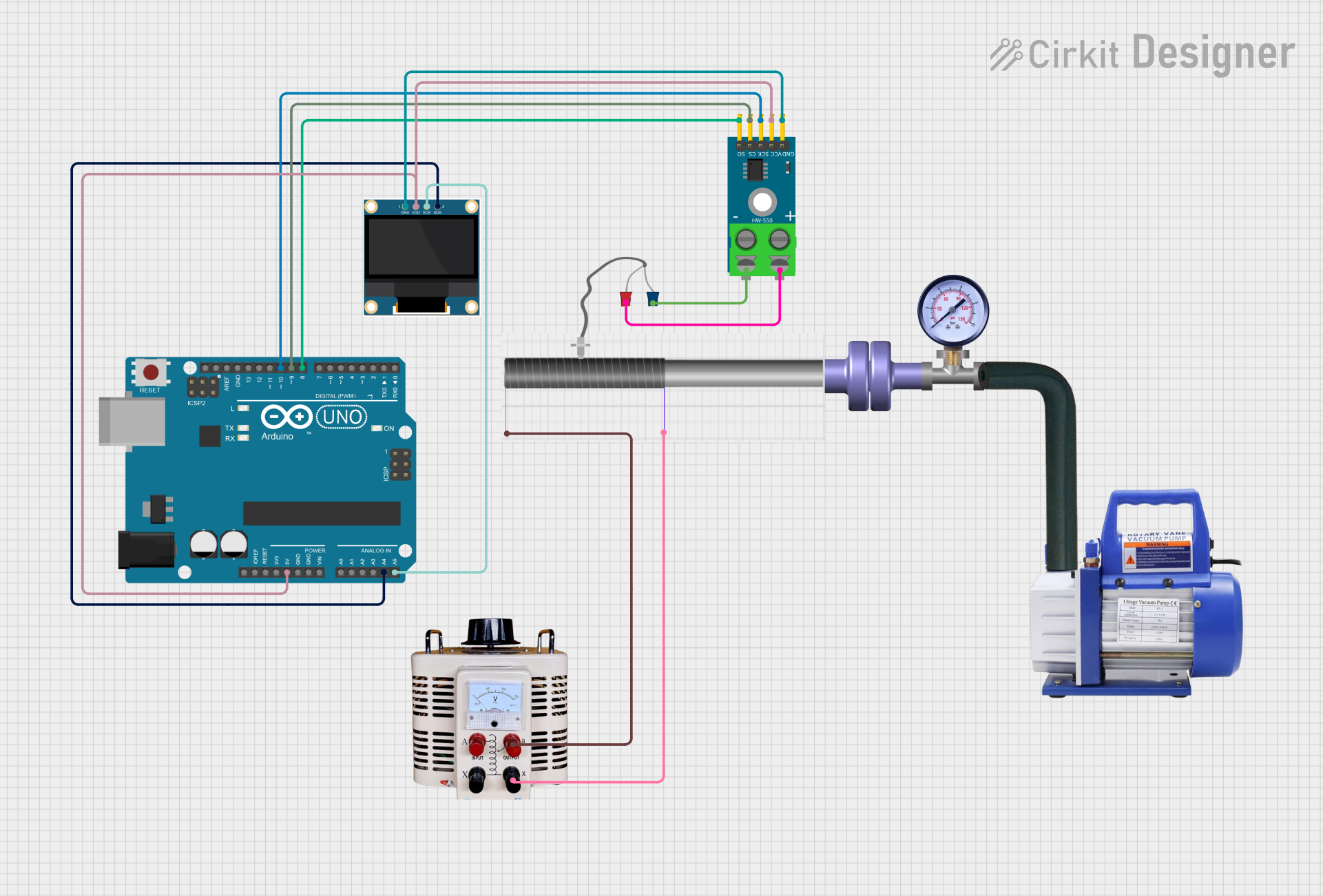
This circuit features an Arduino UNO microcontroller interfaced with a MAX6675 thermocouple module and a 0.96" OLED display. The Arduino reads temperature data from the MAX6675 module, which is connected to a K-type thermocouple, and communicates with the OLED display via I2C to show the temperature readings. Additionally, there are unused components such as a flange, rotary pump, pressure gauge, hose, and a variable transformer connected to a quartz crystal, which do not seem to be integrated into the main functionality of the circuit based on the provided net list and code.
ESP8266 NodeMCU with MAX6675 Thermocouple Interface for Temperature Monitoring
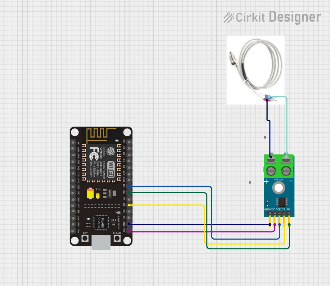
This circuit is designed to measure temperature using a Type K thermocouple connected to a MAX6675 module, which digitizes the temperature reading. The MAX6675 module interfaces with an ESP8266 NodeMCU microcontroller over a SPI connection, using D5 (SCK), D6 (SO), and D8 (CS) for clock, data output, and chip select, respectively. The ESP8266 is responsible for processing the temperature data, which can then be used for monitoring, control, or communication purposes.
Arduino Mega 2560 and MAX6675 Thermocouple Temperature Sensor
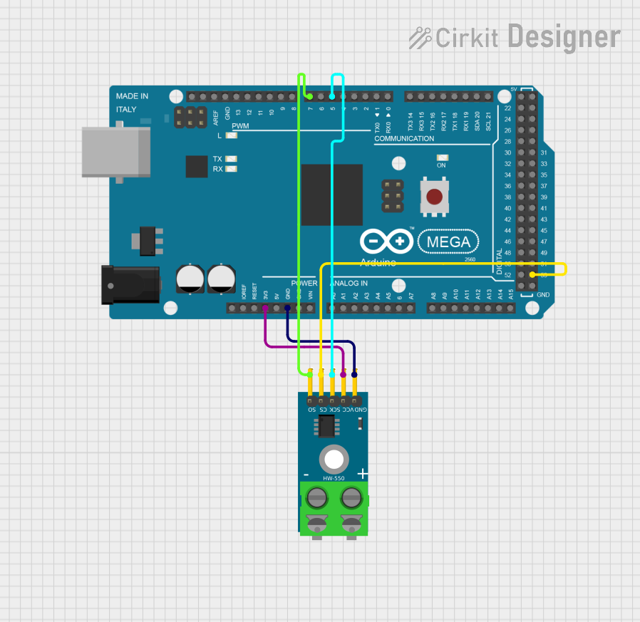
This circuit consists of an Arduino Mega 2560 microcontroller connected to a MAX6675 thermocouple temperature sensor module. The Arduino provides power to the MAX6675 module and reads temperature data via digital pins, enabling temperature monitoring and data acquisition.
Explore Projects Built with Thermocouple
PID Temperature Control System with Thermocouple and SSR
This circuit is a temperature control system that uses a thermocouple to measure temperature and a PID controller to regulate it. The PID controller drives a solid-state relay (SSR) to control an external load, with power supplied through an AC inlet socket.
Arduino UNO Based Temperature Monitoring System with OLED Display
This circuit features an Arduino UNO microcontroller interfaced with a MAX6675 thermocouple module and a 0.96" OLED display. The Arduino reads temperature data from the MAX6675 module, which is connected to a K-type thermocouple, and communicates with the OLED display via I2C to show the temperature readings. Additionally, there are unused components such as a flange, rotary pump, pressure gauge, hose, and a variable transformer connected to a quartz crystal, which do not seem to be integrated into the main functionality of the circuit based on the provided net list and code.
ESP8266 NodeMCU with MAX6675 Thermocouple Interface for Temperature Monitoring
This circuit is designed to measure temperature using a Type K thermocouple connected to a MAX6675 module, which digitizes the temperature reading. The MAX6675 module interfaces with an ESP8266 NodeMCU microcontroller over a SPI connection, using D5 (SCK), D6 (SO), and D8 (CS) for clock, data output, and chip select, respectively. The ESP8266 is responsible for processing the temperature data, which can then be used for monitoring, control, or communication purposes.
Arduino Mega 2560 and MAX6675 Thermocouple Temperature Sensor
This circuit consists of an Arduino Mega 2560 microcontroller connected to a MAX6675 thermocouple temperature sensor module. The Arduino provides power to the MAX6675 module and reads temperature data via digital pins, enabling temperature monitoring and data acquisition.
Common Applications and Use Cases
- Industrial Temperature Monitoring: Used in furnaces, kilns, and other high-temperature environments.
- Scientific Research: Ideal for laboratory experiments requiring precise temperature measurements.
- HVAC Systems: Used to monitor and control heating, ventilation, and air conditioning systems.
- Food Processing: Ensures proper cooking and storage temperatures.
- Automotive: Monitors engine and exhaust temperatures.
Technical Specifications
Key Technical Details
| Parameter | Value |
|---|---|
| Manufacturer | Fluke |
| Part ID | K-Type |
| Temperature Range | -200°C to 1350°C |
| Accuracy | ±1.5°C or ±0.4% |
| Response Time | < 1 second |
| Output Voltage | 0 to 54.886 mV (at 1350°C) |
| Wire Material | Chromel and Alumel |
| Insulation | Fiberglass or Ceramic |
Pin Configuration and Descriptions
| Pin Number | Description |
|---|---|
| 1 | Positive Lead (Chromel, usually red) |
| 2 | Negative Lead (Alumel, usually yellow) |
Usage Instructions
How to Use the Component in a Circuit
Connection to a Microcontroller:
- Connect the positive lead (Chromel) to the analog input pin of the microcontroller.
- Connect the negative lead (Alumel) to the ground (GND) pin of the microcontroller.
Amplification:
- Use a thermocouple amplifier (e.g., MAX6675 or MAX31855) to amplify the small voltage generated by the thermocouple.
- Connect the amplifier output to the microcontroller's analog input pin.
Reading Temperature:
- Use the microcontroller to read the voltage from the thermocouple.
- Convert the voltage to temperature using the appropriate conversion formula or library.
Important Considerations and Best Practices
- Cold Junction Compensation: Ensure proper cold junction compensation to account for the temperature at the connection point.
- Calibration: Regularly calibrate the thermocouple for accurate measurements.
- Shielding: Use shielded cables to minimize electrical noise and interference.
- Proper Installation: Ensure the thermocouple is properly installed and secured in the measurement environment.
Example Code for Arduino UNO
#include <SPI.h>
#include "Adafruit_MAX31855.h"

// Define the pins for the thermocouple amplifier
#define DO   3
#define CS   4
#define CLK  5

// Create an instance of the MAX31855 thermocouple amplifier
Adafruit_MAX31855 thermocouple(CLK, CS, DO);

void setup() {
  Serial.begin(9600);
  while (!Serial) delay(1); // Wait for Serial to be ready

  Serial.println("MAX31855 Thermocouple Test");
  // Check if the thermocouple amplifier is connected
  if (!thermocouple.begin()) {
    Serial.println("Could not find a valid MAX31855 sensor, check wiring!");
    while (1) delay(10);
  }
}

void loop() {
  // Read the temperature in Celsius
  double celsius = thermocouple.readCelsius();
  // Read the temperature in Fahrenheit
  double fahrenheit = thermocouple.readFahrenheit();

  // Check for errors
  if (isnan(celsius)) {
    Serial.println("Error: Could not read temperature data!");
  } else {
    Serial.print("Temperature: ");
    Serial.print(celsius);
    Serial.print(" °C / ");
    Serial.print(fahrenheit);
    Serial.println(" °F");
  }

  delay(1000); // Wait for 1 second before the next reading
}
Troubleshooting and FAQs
Common Issues Users Might Face
Inaccurate Readings:
- Solution: Ensure proper cold junction compensation and calibration. Check for any loose connections or damaged wires.
No Output Voltage:
- Solution: Verify the thermocouple connections and ensure the amplifier is functioning correctly.
Interference and Noise:
- Solution: Use shielded cables and keep the thermocouple away from high-power electrical equipment.
Solutions and Tips for Troubleshooting
- Check Connections: Ensure all connections are secure and correct.
- Use Proper Amplification: Use a suitable thermocouple amplifier to get accurate readings.
- Regular Calibration: Periodically calibrate the thermocouple to maintain accuracy.
- Environmental Factors: Consider the environment where the thermocouple is used, as extreme conditions can affect performance.
By following this documentation, users can effectively utilize the Fluke K-Type Thermocouple in various applications, ensuring accurate and reliable temperature measurements.