How to Use relay ly2n: Examples, Pinouts, and Specs
Introduction
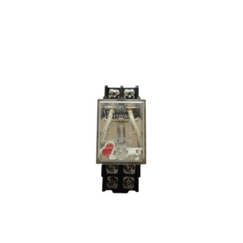
The LY2N is an electromagnetic relay designed to control high-power circuits using low-power signals. It features a dual-contact configuration with both Normally Open (NO) and Normally Closed (NC) terminals, making it versatile for switching electrical loads on and off. The LY2N is widely used in industrial automation, home appliances, and control systems due to its reliability and ease of integration.
Explore Projects Built with relay ly2n
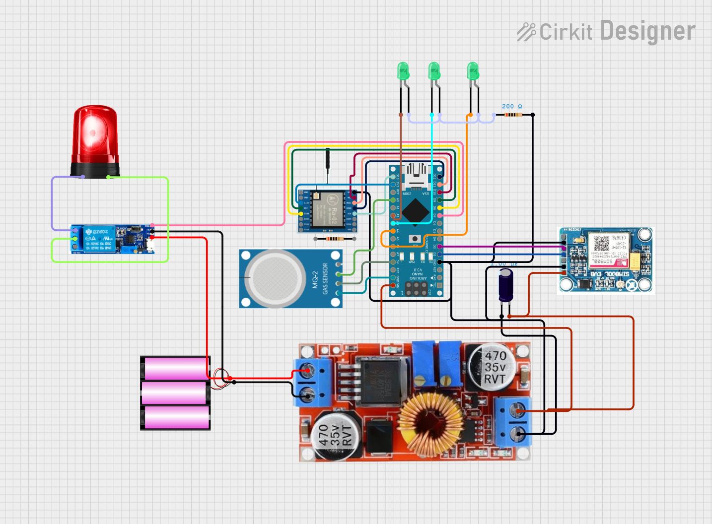
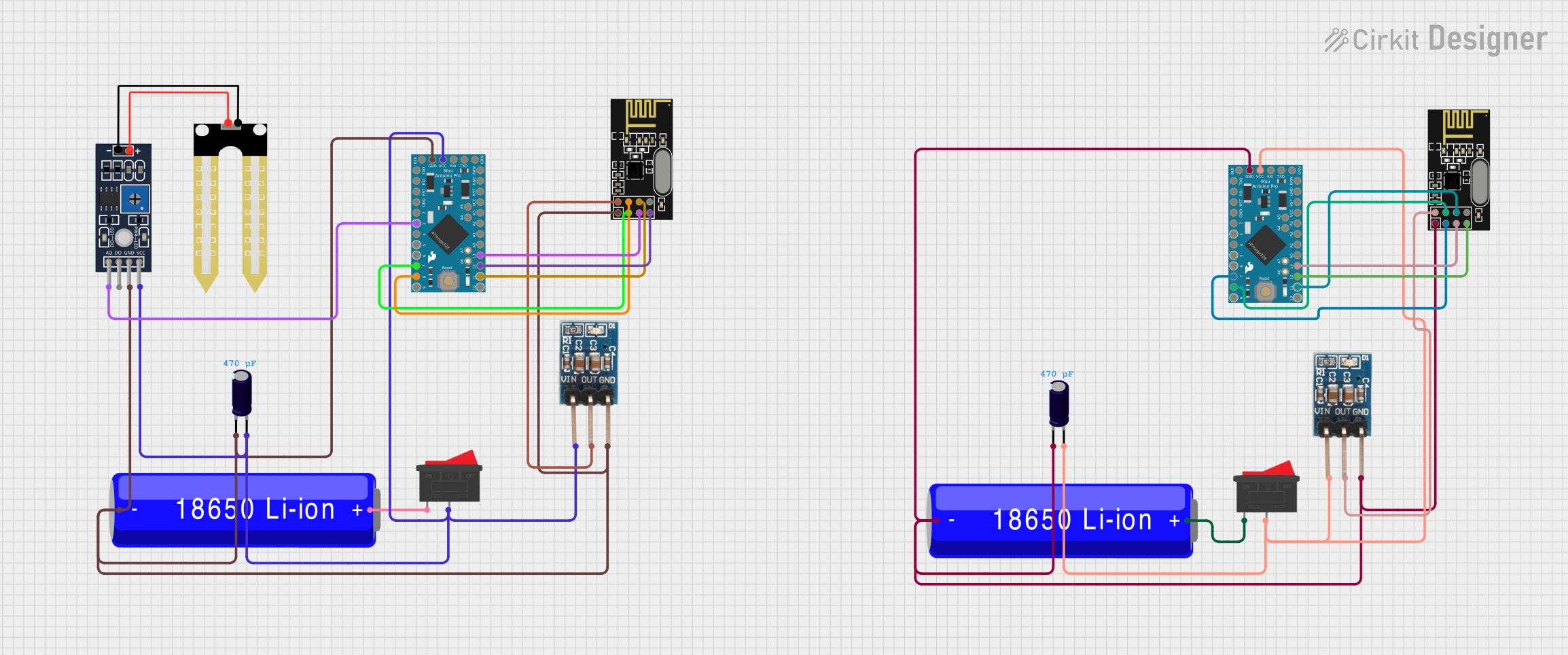

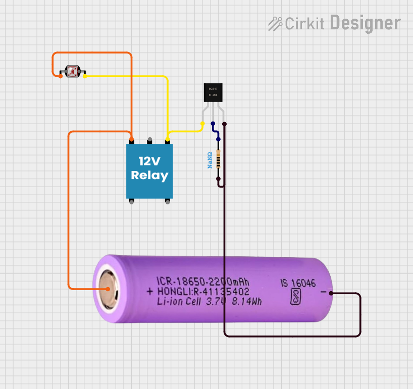
Explore Projects Built with relay ly2n
Common Applications
- Industrial automation systems
- Motor control circuits
- Home appliances (e.g., HVAC systems)
- Lighting control
- Safety and alarm systems
Technical Specifications
Key Technical Details
| Parameter | Value |
|---|---|
| Coil Voltage | 12V DC, 24V DC, 110V AC, etc. |
| Coil Resistance | Varies by model (e.g., 400Ω for 12V DC) |
| Contact Configuration | DPDT (Double Pole Double Throw) |
| Contact Rating | 10A at 250V AC / 10A at 30V DC |
| Dielectric Strength | 2000V AC (coil to contact) |
| Operating Temperature | -40°C to +70°C |
| Mounting Style | Plug-in or PCB mount |
| Dimensions | 28mm x 21.5mm x 35mm |
Pin Configuration and Descriptions
The LY2N relay typically has 8 pins arranged in a rectangular layout. Below is the pinout description:
| Pin Number | Description |
|---|---|
| 1 | Coil Terminal 1 |
| 2 | Coil Terminal 2 |
| 3 | Common Terminal for Pole 1 (COM1) |
| 4 | Normally Closed Contact for Pole 1 (NC1) |
| 5 | Normally Open Contact for Pole 1 (NO1) |
| 6 | Common Terminal for Pole 2 (COM2) |
| 7 | Normally Closed Contact for Pole 2 (NC2) |
| 8 | Normally Open Contact for Pole 2 (NO2) |
Usage Instructions
How to Use the LY2N in a Circuit
- Power the Coil: Connect the relay's coil terminals (pins 1 and 2) to a power source that matches the relay's rated coil voltage (e.g., 12V DC). Use a current-limiting resistor if necessary.
- Connect the Load:
- For a Normally Open (NO) configuration, connect the load between the NO terminal (pin 5 or 8) and the Common terminal (pin 3 or 6).
- For a Normally Closed (NC) configuration, connect the load between the NC terminal (pin 4 or 7) and the Common terminal (pin 3 or 6).
- Control the Relay: Apply a voltage to the coil terminals to energize the relay. This will switch the contacts from their default state (NC to NO or vice versa).
Important Considerations
- Back-EMF Protection: When using the relay with a DC coil, always include a flyback diode across the coil terminals to protect the driving circuit from voltage spikes.
- Contact Ratings: Ensure the load current and voltage do not exceed the relay's contact ratings to avoid damage.
- Isolation: Use optocouplers or transistors to isolate the control circuit from the relay if necessary.
Example: Connecting LY2N to an Arduino UNO
Below is an example of how to control the LY2N relay using an Arduino UNO:
// Example: Controlling LY2N Relay with Arduino UNO
// Pin 7 of Arduino is used to control the relay

const int relayPin = 7; // Define the pin connected to the relay module

void setup() {
  pinMode(relayPin, OUTPUT); // Set relay pin as output
  digitalWrite(relayPin, LOW); // Ensure relay is off at startup
}

void loop() {
  digitalWrite(relayPin, HIGH); // Turn relay on
  delay(1000); // Keep relay on for 1 second
  digitalWrite(relayPin, LOW); // Turn relay off
  delay(1000); // Keep relay off for 1 second
}
Note: Use a transistor or relay driver module to interface the Arduino with the relay, as the Arduino's GPIO pins cannot directly supply enough current to energize the relay coil.
Troubleshooting and FAQs
Common Issues and Solutions
Relay Not Switching:
- Cause: Insufficient voltage or current to the coil.
- Solution: Verify the power supply matches the relay's coil voltage and can provide adequate current.
Contacts Sticking:
- Cause: Overloading the relay contacts.
- Solution: Ensure the load does not exceed the relay's contact ratings.
Noise or Chattering:
- Cause: Unstable control signal or insufficient coil voltage.
- Solution: Use a stable power source and check for loose connections.
Coil Overheating:
- Cause: Continuous overvoltage to the coil.
- Solution: Verify the input voltage and use a resistor if necessary.
FAQs
Q: Can the LY2N relay handle AC loads?
A: Yes, the LY2N can handle AC loads up to 250V, provided the current does not exceed 10A.Q: Do I need a separate power supply for the relay coil?
A: Yes, the relay coil requires a power supply that matches its rated voltage (e.g., 12V DC).Q: Can I use the LY2N relay for switching low-power signals?
A: While it is possible, the LY2N is better suited for high-power applications. For low-power signals, consider using a solid-state relay (SSR).Q: How do I mount the LY2N relay?
A: The LY2N can be mounted on a PCB or used with a compatible relay socket for easy installation and replacement.