How to Use Arduino NANO_ww: Examples, Pinouts, and Specs
Introduction
The Arduino Nano is a compact, breadboard-friendly microcontroller board based on the ATmega328P. It is widely used for prototyping and DIY electronics projects due to its small size and versatility. The Nano is similar to the Arduino Uno but in a smaller form factor, making it ideal for projects where space is limited.
Explore Projects Built with Arduino NANO_ww
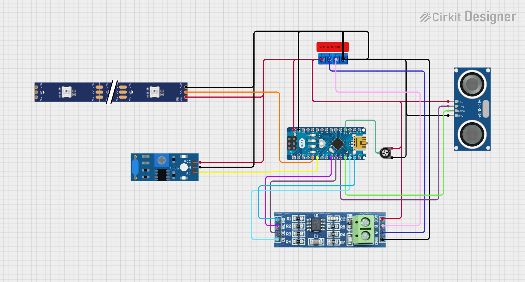
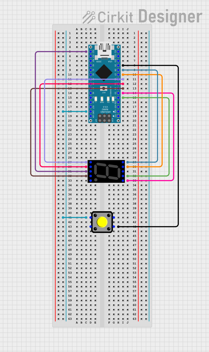
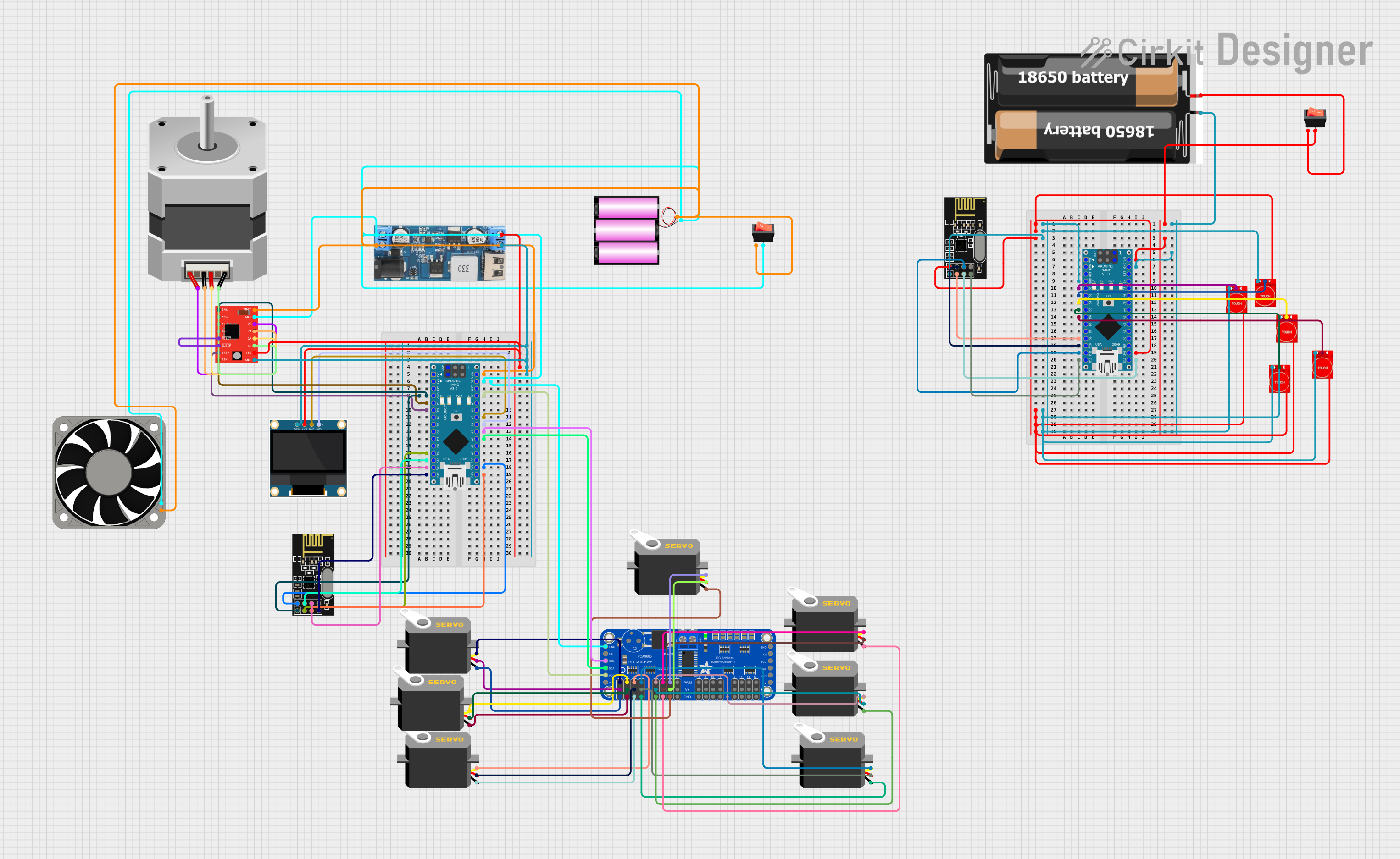
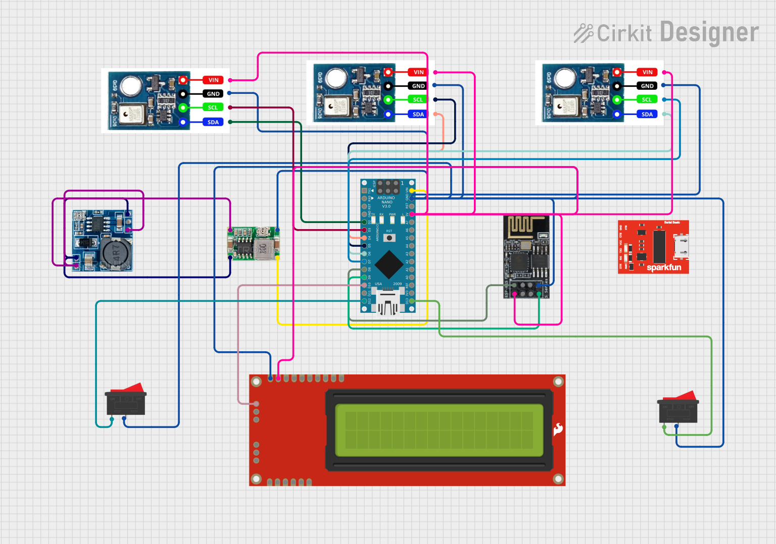
Explore Projects Built with Arduino NANO_ww
Common Applications and Use Cases
- Prototyping: Ideal for testing and developing new electronic circuits.
- DIY Projects: Perfect for hobbyists building custom electronics.
- Wearable Electronics: Its small size makes it suitable for wearable tech.
- Educational Purposes: Great for learning and teaching electronics and programming.
- Embedded Systems: Can be used in various embedded applications due to its versatility.
Technical Specifications
Key Technical Details
| Specification | Value |
|---|---|
| Microcontroller | ATmega328P |
| Operating Voltage | 5V |
| Input Voltage | 7-12V |
| Digital I/O Pins | 14 (of which 6 provide PWM) |
| Analog Input Pins | 8 |
| DC Current per I/O Pin | 40 mA |
| Flash Memory | 32 KB (ATmega328P) |
| SRAM | 2 KB (ATmega328P) |
| EEPROM | 1 KB (ATmega328P) |
| Clock Speed | 16 MHz |
| Dimensions | 18 x 45 mm |
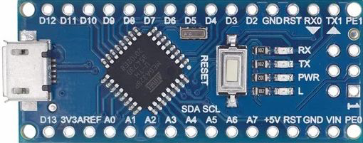
Pin Configuration and Descriptions
| Pin Number | Pin Name | Description |
|---|---|---|
| 1 | D1 | Digital I/O Pin 1 |
| 2 | D2 | Digital I/O Pin 2 |
| 3 | D3 | Digital I/O Pin 3 (PWM) |
| 4 | D4 | Digital I/O Pin 4 |
| 5 | D5 | Digital I/O Pin 5 (PWM) |
| 6 | D6 | Digital I/O Pin 6 (PWM) |
| 7 | D7 | Digital I/O Pin 7 |
| 8 | D8 | Digital I/O Pin 8 |
| 9 | D9 | Digital I/O Pin 9 (PWM) |
| 10 | D10 | Digital I/O Pin 10 (PWM) |
| 11 | D11 | Digital I/O Pin 11 (PWM) |
| 12 | D12 | Digital I/O Pin 12 |
| 13 | D13 | Digital I/O Pin 13 (LED) |
| 14 | A0 | Analog Input Pin 0 |
| 15 | A1 | Analog Input Pin 1 |
| 16 | A2 | Analog Input Pin 2 |
| 17 | A3 | Analog Input Pin 3 |
| 18 | A4 | Analog Input Pin 4 (SDA) |
| 19 | A5 | Analog Input Pin 5 (SCL) |
| 20 | A6 | Analog Input Pin 6 |
| 21 | A7 | Analog Input Pin 7 |
| 22 | VIN | Input Voltage (7-12V) |
| 23 | GND | Ground |
| 24 | 5V | 5V Output |
| 25 | 3.3V | 3.3V Output |
| 26 | RST | Reset |
| 27 | TX | Transmit (UART) |
| 28 | RX | Receive (UART) |
Usage Instructions
How to Use the Component in a Circuit
Powering the Arduino Nano:
- Connect the VIN pin to a 7-12V power source.
- Alternatively, you can power the Nano via the USB port.
Connecting Digital I/O:
- Use digital pins (D0-D13) for digital input/output operations.
- Pins D3, D5, D6, D9, D10, and D11 support PWM.
Connecting Analog Inputs:
- Use analog pins (A0-A7) for reading analog signals.
Serial Communication:
- Use TX (D1) and RX (D0) for UART communication.
Important Considerations and Best Practices
- Avoid Overloading Pins: Ensure that the current drawn from any I/O pin does not exceed 40 mA.
- Proper Grounding: Always connect the GND pin to the ground of your circuit.
- Voltage Levels: Ensure that the input voltage to the VIN pin is within the 7-12V range.
- Resetting the Board: Use the RST pin or the reset button to reset the board if needed.
Example Code
Here is a simple example code to blink an LED connected to pin D13:
// Define the LED pin
const int ledPin = 13;

void setup() {
  // Initialize the digital pin as an output
  pinMode(ledPin, OUTPUT);
}

void loop() {
  // Turn the LED on (HIGH is the voltage level)
  digitalWrite(ledPin, HIGH);
  // Wait for a second
  delay(1000);
  // Turn the LED off by making the voltage LOW
  digitalWrite(ledPin, LOW);
  // Wait for a second
  delay(1000);
}
Troubleshooting and FAQs
Common Issues Users Might Face
Board Not Recognized by Computer:
- Ensure the correct drivers are installed.
- Check the USB cable and port.
Upload Errors:
- Verify the correct board and port are selected in the Arduino IDE.
- Ensure no other program is using the serial port.
Unresponsive Board:
- Try resetting the board using the reset button.
- Check for any short circuits or incorrect connections.
Solutions and Tips for Troubleshooting
- Check Connections: Ensure all connections are secure and correct.
- Use a Different USB Cable/Port: Sometimes the issue can be with the USB cable or port.
- Reinstall Drivers: Reinstall the Arduino drivers if the board is not recognized.
- Consult the Community: The Arduino community is very active and can be a great resource for troubleshooting.
By following this documentation, users should be able to effectively utilize the Arduino Nano in their projects, troubleshoot common issues, and understand the key technical details and best practices for using this versatile microcontroller board.