Cirkit Designer Logo
Cirkit Designer
Your all-in-one circuit design IDE
Home / 
Component Documentation

How to Use MX1508: Examples, Pinouts, and Specs

Image of MX1508
Cirkit Designer LogoDesign with MX1508 in Cirkit Designer

Introduction

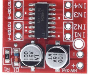
The MX1508 is a dual operational amplifier (op-amp) designed for low-power applications. It offers high gain, low noise, and a wide bandwidth, making it an excellent choice for signal conditioning, filtering, and amplification tasks in various electronic circuits. Its compact design and reliable performance make it suitable for use in audio processing, sensor signal amplification, and analog computing applications.

Explore Projects Built with MX1508

Use Cirkit Designer to design, explore, and prototype these projects online. Some projects support real-time simulation. Click "Open Project" to start designing instantly!
WiFi-Controlled Basket-Carrying Robot with GPS and GSM Notification
Image of trash collecting vessel: A project utilizing MX1508 in a practical application
This circuit is designed for a 4-wheeled WiFi-controlled car with a basket, which uses an ESP8266 NodeMCU microcontroller for logic control. It features an IR sensor for basket full detection, a GPS module for location tracking, and a GSM module (Sim800l) for sending SMS notifications. The L298N motor driver controls four DC gearmotors for movement, and the system is powered by a Li-ion battery with a 7805 voltage regulator providing stable power to the GSM module.
Cirkit Designer LogoOpen Project in Cirkit Designer
ESP32C3-Based Multi-Sensor Data Logger with Wi-Fi and SD Card Storage
Image of Petora_v1: A project utilizing MX1508 in a practical application
This circuit is a data logging and transmission system that collects environmental and positional data from various sensors (BME/BMP280, HMC5883L, MAX30102, GPS NEO 6M) and records it to an SD card. The data is also sent over WiFi to a specified server using an ESP32 microcontroller.
Cirkit Designer LogoOpen Project in Cirkit Designer
Arduino Mega 2560 Based Security System with Fingerprint Authentication and SMS Alerts
Image of Door security system: A project utilizing MX1508 in a practical application
This circuit features an Arduino Mega 2560 microcontroller interfaced with a SIM800L GSM module, two fingerprint scanners, an I2C LCD display, an IR sensor, and a piezo buzzer. Power management is handled by a PowerBoost 1000 Basic Pad USB, a TP4056 charging module, and a Li-ion 18650 battery, with an option to use a Mini AC-DC 110V-230V to 5V 700mA module for direct power supply. The primary functionality appears to be a security system with GSM communication capabilities, biometric access control, and visual/audible feedback.
Cirkit Designer LogoOpen Project in Cirkit Designer
ESP32-Controlled Traffic Light and Multi-Motor Driver System
Image of Projeto final: A project utilizing MX1508 in a practical application
This circuit features an ESP32 microcontroller connected to a traffic light module and multiple DC motors via two L298N motor drivers. The ESP32 controls the traffic light states and motor operations, likely for a model intersection with moving parts. The circuit also includes MT3608 boost converters to step up the voltage from a 4 x AAA battery mount to the required levels for the motor drivers, and an MG996R servo motor controlled directly by the ESP32.
Cirkit Designer LogoOpen Project in Cirkit Designer

Explore Projects Built with MX1508

Use Cirkit Designer to design, explore, and prototype these projects online. Some projects support real-time simulation. Click "Open Project" to start designing instantly!
Image of trash collecting vessel: A project utilizing MX1508 in a practical application
WiFi-Controlled Basket-Carrying Robot with GPS and GSM Notification
This circuit is designed for a 4-wheeled WiFi-controlled car with a basket, which uses an ESP8266 NodeMCU microcontroller for logic control. It features an IR sensor for basket full detection, a GPS module for location tracking, and a GSM module (Sim800l) for sending SMS notifications. The L298N motor driver controls four DC gearmotors for movement, and the system is powered by a Li-ion battery with a 7805 voltage regulator providing stable power to the GSM module.
Cirkit Designer LogoOpen Project in Cirkit Designer
Image of Petora_v1: A project utilizing MX1508 in a practical application
ESP32C3-Based Multi-Sensor Data Logger with Wi-Fi and SD Card Storage
This circuit is a data logging and transmission system that collects environmental and positional data from various sensors (BME/BMP280, HMC5883L, MAX30102, GPS NEO 6M) and records it to an SD card. The data is also sent over WiFi to a specified server using an ESP32 microcontroller.
Cirkit Designer LogoOpen Project in Cirkit Designer
Image of Door security system: A project utilizing MX1508 in a practical application
Arduino Mega 2560 Based Security System with Fingerprint Authentication and SMS Alerts
This circuit features an Arduino Mega 2560 microcontroller interfaced with a SIM800L GSM module, two fingerprint scanners, an I2C LCD display, an IR sensor, and a piezo buzzer. Power management is handled by a PowerBoost 1000 Basic Pad USB, a TP4056 charging module, and a Li-ion 18650 battery, with an option to use a Mini AC-DC 110V-230V to 5V 700mA module for direct power supply. The primary functionality appears to be a security system with GSM communication capabilities, biometric access control, and visual/audible feedback.
Cirkit Designer LogoOpen Project in Cirkit Designer
Image of Projeto final: A project utilizing MX1508 in a practical application
ESP32-Controlled Traffic Light and Multi-Motor Driver System
This circuit features an ESP32 microcontroller connected to a traffic light module and multiple DC motors via two L298N motor drivers. The ESP32 controls the traffic light states and motor operations, likely for a model intersection with moving parts. The circuit also includes MT3608 boost converters to step up the voltage from a 4 x AAA battery mount to the required levels for the motor drivers, and an MG996R servo motor controlled directly by the ESP32.
Cirkit Designer LogoOpen Project in Cirkit Designer

Common Applications and Use Cases

  • Signal conditioning for sensors
  • Audio signal amplification
  • Active filters (low-pass, high-pass, band-pass)
  • Analog computation circuits
  • Voltage followers and buffer circuits

Technical Specifications

The MX1508 is designed to meet the needs of low-power and high-performance applications. Below are its key technical specifications:

Parameter Value
Supply Voltage (Vcc) 3V to 15V (single supply)
Input Offset Voltage ≤ 5 mV
Input Bias Current ≤ 250 nA
Gain Bandwidth Product 1 MHz
Slew Rate 0.5 V/µs
Output Voltage Swing 0V to (Vcc - 1.5V)
Operating Temperature -40°C to +85°C
Package Type DIP-8, SOIC-8

Pin Configuration and Descriptions

The MX1508 is typically available in an 8-pin package. Below is the pinout and description:

Pin Number Pin Name Description
1 OUT1 Output of Op-Amp 1
2 IN1- Inverting input of Op-Amp 1
3 IN1+ Non-inverting input of Op-Amp 1
4 VSS Negative power supply (or ground for single supply)
5 IN2+ Non-inverting input of Op-Amp 2
6 IN2- Inverting input of Op-Amp 2
7 OUT2 Output of Op-Amp 2
8 VDD Positive power supply

Usage Instructions

The MX1508 is straightforward to use in a variety of circuit configurations. Below are the steps and considerations for using the component effectively:

How to Use the MX1508 in a Circuit

  1. Power Supply: Connect the VDD pin to the positive supply voltage (3V to 15V) and the VSS pin to the negative supply voltage or ground (for single-supply operation).
  2. Input Connections:
    • For inverting configurations, connect the input signal to the IN- pin through a resistor.
    • For non-inverting configurations, connect the input signal directly to the IN+ pin.
  3. Output Connections: Connect the OUT pin to the desired load or the next stage of the circuit.
  4. Feedback Network: Use resistors and/or capacitors between the output and input pins to set the gain and frequency response of the amplifier.

Important Considerations and Best Practices

  • Power Supply Decoupling: Place a 0.1 µF ceramic capacitor close to the VDD and VSS pins to reduce noise and improve stability.
  • Input Impedance: Ensure the input impedance of the circuit matches the requirements of the MX1508 to avoid signal distortion.
  • Output Loading: Avoid connecting loads that exceed the output current capability of the op-amp.
  • Thermal Management: Operate the MX1508 within its specified temperature range to ensure reliable performance.

Example: Connecting the MX1508 to an Arduino UNO

The MX1508 can be used with an Arduino UNO for signal amplification. Below is an example of a simple non-inverting amplifier circuit:

Circuit Description

  • The input signal is connected to the IN+ pin of the MX1508.
  • The output of the MX1508 is connected to an analog input pin of the Arduino UNO for signal monitoring.

Arduino Code Example

// Example code to read an amplified signal from the MX1508 using Arduino UNO

const int analogPin = A0; // Analog pin connected to MX1508 output
int signalValue = 0;      // Variable to store the analog signal value

void setup() {
  Serial.begin(9600); // Initialize serial communication at 9600 baud
}

void loop() {
  signalValue = analogRead(analogPin); // Read the amplified signal
  Serial.print("Signal Value: ");      // Print the signal value to the serial monitor
  Serial.println(signalValue);
  delay(100); // Delay for 100ms before the next reading
}

Troubleshooting and FAQs

Common Issues and Solutions

  1. No Output Signal:

    • Cause: Incorrect power supply connections.
    • Solution: Verify that VDD and VSS are connected to the correct voltage levels.
  2. Distorted Output Signal:

    • Cause: Input signal exceeds the input voltage range.
    • Solution: Ensure the input signal is within the specified range of the MX1508.
  3. Excessive Noise:

    • Cause: Insufficient power supply decoupling.
    • Solution: Add a 0.1 µF ceramic capacitor close to the power supply pins.
  4. Overheating:

    • Cause: Operating the MX1508 beyond its maximum ratings.
    • Solution: Ensure the supply voltage and output current are within the specified limits.

FAQs

Q1: Can the MX1508 operate with a single power supply?
A1: Yes, the MX1508 can operate with a single supply voltage. Connect VSS to ground and VDD to the positive supply voltage.

Q2: What is the maximum gain achievable with the MX1508?
A2: The maximum gain depends on the external feedback network. Theoretically, the gain can be very high, but practical limitations such as bandwidth and stability must be considered.

Q3: Can the MX1508 be used for audio applications?
A3: Yes, the MX1508 is suitable for audio signal amplification due to its low noise and high gain characteristics.

Q4: How do I calculate the gain of the MX1508 in a non-inverting configuration?
A4: The gain is calculated using the formula: Gain = 1 + (Rf / Rin), where Rf is the feedback resistor and Rin is the input resistor.