
How to Use MicoAir743v2: Examples, Pinouts, and Specs
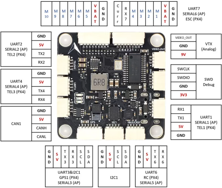
 Design with MicoAir743v2 in Cirkit Designer
Introduction
The MicoAir743v2 is a compact, low-power wireless communication module designed for Internet of Things (IoT) applications. Manufactured by MicoAir, this module offers advanced connectivity options and efficient data transmission capabilities, making it ideal for a wide range of wireless communication needs. Its small form factor and energy-efficient design make it particularly suitable for battery-powered devices and embedded systems.
Explore Projects Built with MicoAir743v2
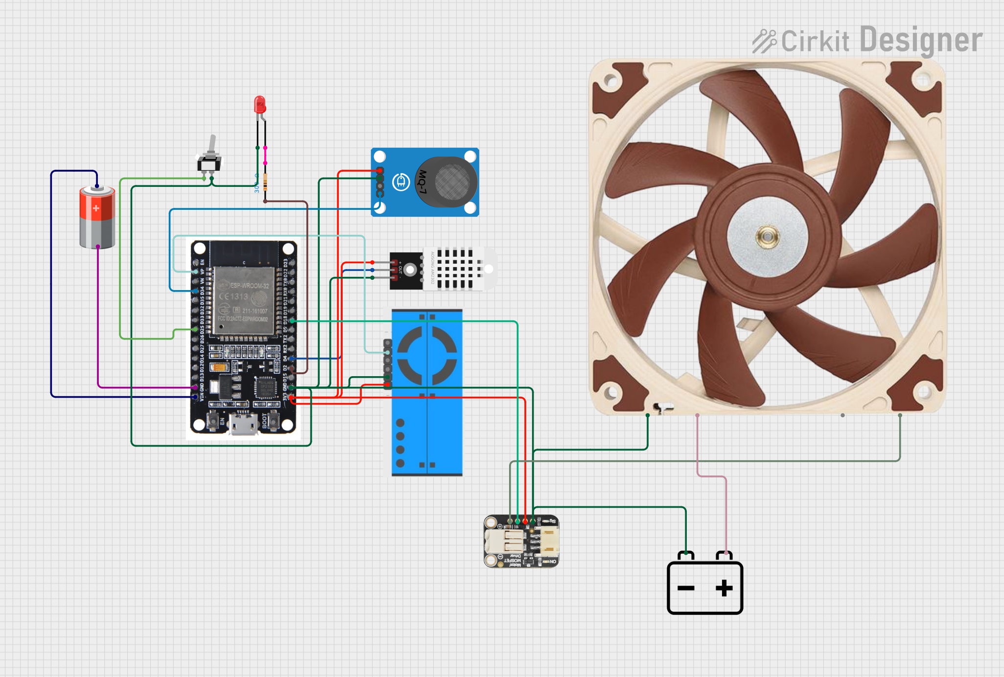 Open Project in Cirkit Designer
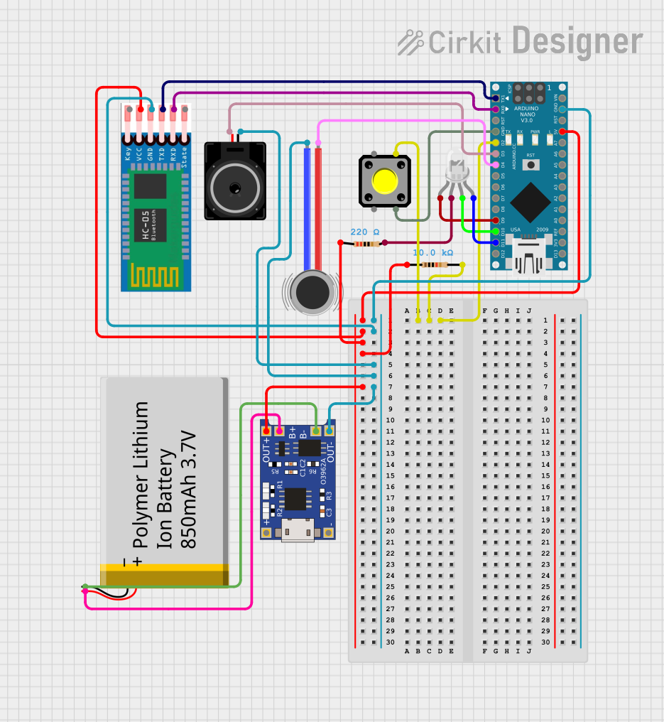 Open Project in Cirkit Designer
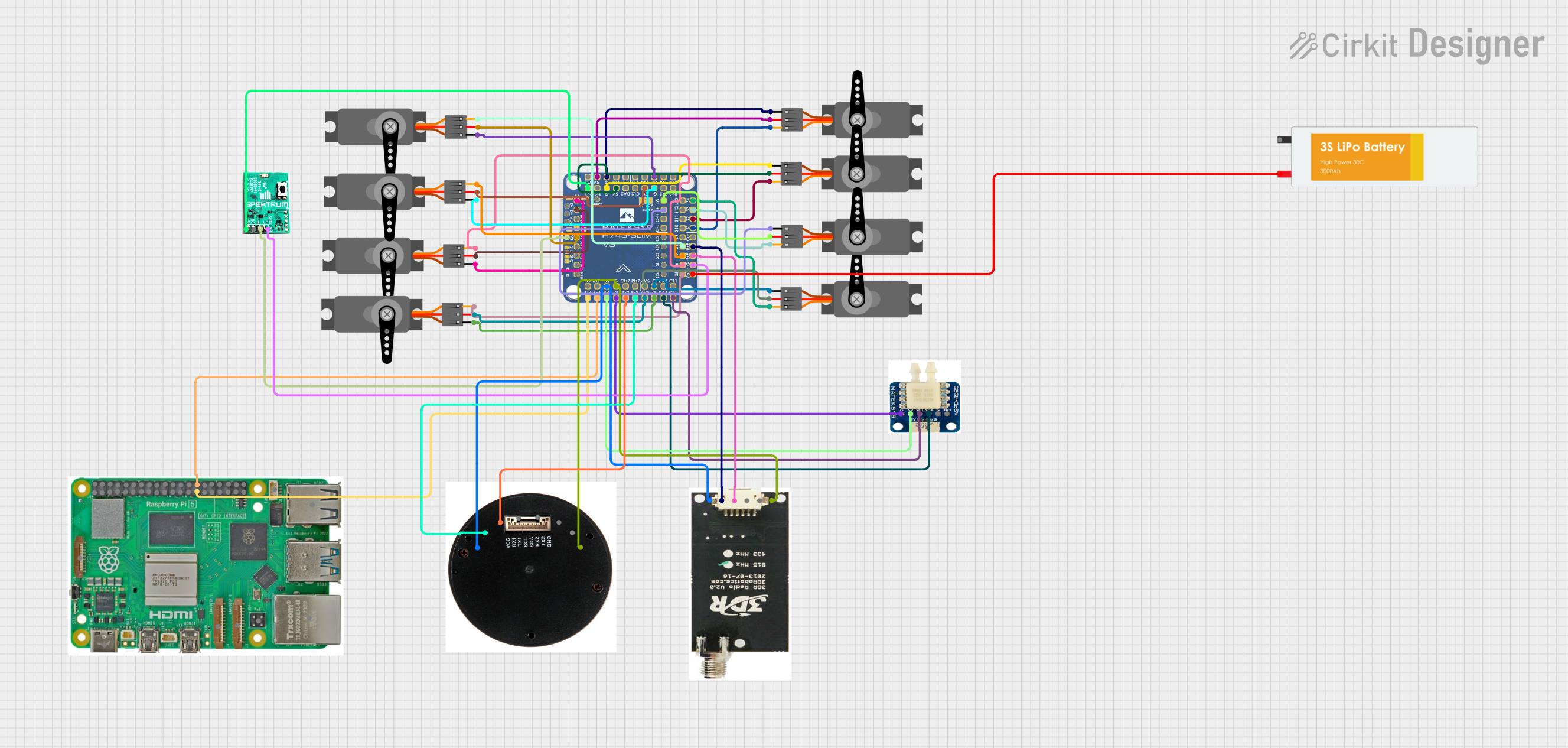 Open Project in Cirkit Designer
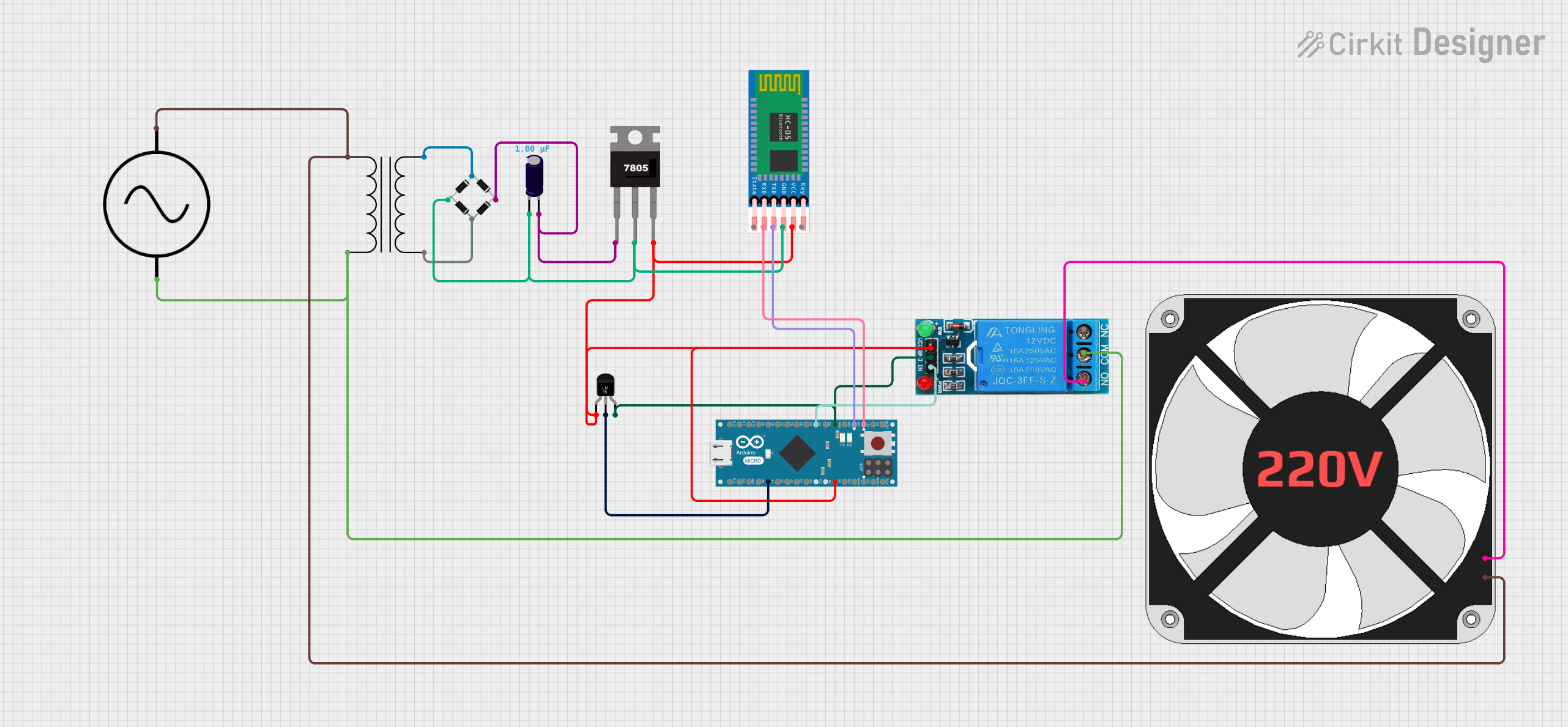 Open Project in Cirkit Designer
Explore Projects Built with MicoAir743v2
Open Project in Cirkit DesignerOpen Project in Cirkit DesignerOpen Project in Cirkit DesignerOpen Project in Cirkit DesignerCommon Applications and Use Cases
- Smart home devices (e.g., smart thermostats, lighting systems)
- Industrial IoT (e.g., sensor networks, asset tracking)
- Wearable technology
- Remote monitoring and control systems
- Wireless data logging and telemetry
Technical Specifications
The MicoAir743v2 is engineered to deliver reliable performance in a variety of environments. Below are its key technical specifications:
| Parameter | Value |
|---|---|
| Manufacturer | MicoAir |
| Part ID | MicoAir743v2 |
| Wireless Protocols | Wi-Fi (802.11 b/g/n), Bluetooth 5.0 |
| Operating Voltage | 3.3V |
| Power Consumption | 10 mA (idle), 120 mA (transmit) |
| Operating Temperature | -40°C to +85°C |
| Data Rate | Up to 150 Mbps (Wi-Fi) |
| Dimensions | 18 mm x 15 mm x 3 mm |
| Antenna | Integrated PCB antenna |
| Interface | UART, SPI, I2C |
| Flash Memory | 4 MB |
| RAM | 512 KB |
Pin Configuration and Descriptions
The MicoAir743v2 module has 12 pins, each serving a specific function. The table below provides details:
| Pin Number | Pin Name | Description |
|---|---|---|
| 1 | GND | Ground |
| 2 | VCC | Power supply (3.3V) |
| 3 | TX | UART Transmit |
| 4 | RX | UART Receive |
| 5 | GPIO0 | General-purpose I/O |
| 6 | GPIO1 | General-purpose I/O |
| 7 | SPI_MOSI | SPI Master Out Slave In |
| 8 | SPI_MISO | SPI Master In Slave Out |
| 9 | SPI_CLK | SPI Clock |
| 10 | I2C_SCL | I2C Clock |
| 11 | I2C_SDA | I2C Data |
| 12 | RESET | Module Reset (active low) |
Usage Instructions
How to Use the MicoAir743v2 in a Circuit
- Power Supply: Connect the VCC pin to a stable 3.3V power source and the GND pin to ground.
- Communication Interface: Choose the appropriate communication protocol (UART, SPI, or I2C) based on your application:
- For UART, connect the TX and RX pins to the corresponding pins on your microcontroller.
- For SPI, connect SPI_MOSI, SPI_MISO, and SPI_CLK to the respective SPI pins on your microcontroller.
- For I2C, connect I2C_SCL and I2C_SDA to the corresponding I2C pins on your microcontroller.
- Antenna: The module includes an integrated PCB antenna, so no external antenna is required.
- Reset: Optionally, connect the RESET pin to a GPIO pin on your microcontroller for manual or software-controlled resets.
Important Considerations and Best Practices
- Ensure the power supply is clean and stable to avoid communication errors.
- Use pull-up resistors on the I2C lines (SCL and SDA) if they are not already included in your circuit.
- Place the module away from sources of electromagnetic interference (EMI) to maintain signal integrity.
- Avoid placing metal objects near the integrated antenna to prevent signal degradation.
Example: Connecting to an Arduino UNO
Below is an example of how to connect the MicoAir743v2 to an Arduino UNO using UART:
Wiring Diagram
| MicoAir743v2 Pin | Arduino UNO Pin |
|---|---|
| VCC | 3.3V |
| GND | GND |
| TX | Pin 10 (RX) |
| RX | Pin 11 (TX) |
| RESET | Pin 12 |
Arduino Code Example
#include <SoftwareSerial.h>

// Define RX and TX pins for SoftwareSerial
SoftwareSerial MicoAir(10, 11); // RX, TX

void setup() {
  // Initialize serial communication with the module
  MicoAir.begin(9600); // Set baud rate to 9600
  Serial.begin(9600);  // For debugging via Serial Monitor

  // Reset the module
  pinMode(12, OUTPUT); // Set RESET pin as output
  digitalWrite(12, LOW); // Pull RESET pin low
  delay(100);           // Wait for 100 ms
  digitalWrite(12, HIGH); // Release RESET pin
  delay(500);           // Wait for the module to initialize

  Serial.println("MicoAir743v2 initialized.");
}

void loop() {
  // Send a test message to the module
  MicoAir.println("Hello, MicoAir743v2!");

  // Check for incoming data from the module
  if (MicoAir.available()) {
    String response = MicoAir.readString();
    Serial.println("Response from MicoAir743v2: " + response);
  }

  delay(1000); // Wait 1 second before sending the next message
}
Troubleshooting and FAQs
Common Issues and Solutions
Module Not Responding
- Cause: Incorrect wiring or insufficient power supply.
- Solution: Double-check all connections and ensure the power supply provides a stable 3.3V.
Communication Errors
- Cause: Mismatched baud rate or noisy power supply.
- Solution: Verify the baud rate in your code matches the module's default (9600 bps). Use decoupling capacitors near the power pins to reduce noise.
Weak Signal Strength
- Cause: Obstructions or interference near the antenna.
- Solution: Relocate the module to a position with fewer obstructions and away from EMI sources.
I2C or SPI Not Working
- Cause: Missing pull-up resistors or incorrect pin connections.
- Solution: Add pull-up resistors (4.7kΩ to 10kΩ) to the I2C lines. Verify SPI connections are correct.
FAQs
Q: Can the MicoAir743v2 operate at 5V?
A: No, the module is designed to operate at 3.3V. Using 5V may damage the module.Q: Does the module support external antennas?
A: No, the MicoAir743v2 includes an integrated PCB antenna and does not support external antennas.Q: What is the maximum range of the module?
A: The range depends on the environment but typically extends up to 50 meters indoors and 150 meters outdoors in line-of-sight conditions.Q: Can I update the firmware on the MicoAir743v2?
A: Yes, firmware updates can be performed via the UART interface. Refer to the manufacturer's firmware update guide for details.