Cirkit Designer Logo
Cirkit Designer
Your all-in-one circuit design IDE
Home / 
Component Documentation

How to Use Adafruit 4-channel I2C-safe Bi-directional Logic Level Converter: Examples, Pinouts, and Specs

Image of Adafruit 4-channel I2C-safe Bi-directional Logic Level Converter
Cirkit Designer LogoDesign with Adafruit 4-channel I2C-safe Bi-directional Logic Level Converter in Cirkit Designer

Introduction

The Adafruit 4-Channel I2C-Safe Bi-directional Logic Level Converter is a small device that safely steps down 5V signals to 3.3V and steps up 3.3V to 5V simultaneously. This level converter is specifically designed to interface with I2C, a popular communication protocol, which makes it ideal for connecting a 3.3V device to a 5V system without any worry of damage. Common applications include interfacing 5V microcontrollers with 3.3V sensors, or vice versa.

Explore Projects Built with Adafruit 4-channel I2C-safe Bi-directional Logic Level Converter

Use Cirkit Designer to design, explore, and prototype these projects online. Some projects support real-time simulation. Click "Open Project" to start designing instantly!
Raspberry Pi 4B and mlx90614 Infrared Thermometer with Logic Level Conversion
Image of thermal Sensor: A project utilizing Adafruit 4-channel I2C-safe Bi-directional Logic Level Converter in a practical application
This circuit connects a Raspberry Pi 4B to an MLX90614 infrared temperature sensor using an Adafruit 4-channel I2C-safe Bi-directional Logic Level Converter. The level converter is used to safely step down the 5V I2C signals from the Raspberry Pi to the 3.3V needed by the MLX90614 sensor, ensuring compatibility between the devices. Ground connections are shared among all components, and the sensor is powered by the Raspberry Pi's 5V supply through the level converter.
Cirkit Designer LogoOpen Project in Cirkit Designer
ESP32 and Logic Level Converter-Based Wi-Fi Controlled Interface
Image of Toshiba AC ESP32 devkit v1: A project utilizing Adafruit 4-channel I2C-safe Bi-directional Logic Level Converter in a practical application
This circuit features an ESP32 Devkit V1 microcontroller connected to a Bi-Directional Logic Level Converter, which facilitates voltage level shifting between the ESP32 and external components. The ESP32 is powered through its VIN pin via an alligator clip cable, and the logic level converter is connected to various pins on the ESP32 to manage different voltage levels for communication.
Cirkit Designer LogoOpen Project in Cirkit Designer
Arduino Mega 2560 Controlled Motor System with I2C Communication and Hall Effect Sensing
Image of Uni1: A project utilizing Adafruit 4-channel I2C-safe Bi-directional Logic Level Converter in a practical application
This is a motor control system with feedback and sensor integration. It uses an Arduino Mega 2560 to control MD03 motor drivers for DC motors, receives position and speed feedback from HEDS encoders and Hall sensors, and measures distance with SR02 ultrasonic sensors. Logic level converters ensure compatibility between different voltage levels of the components.
Cirkit Designer LogoOpen Project in Cirkit Designer
Arduino Mega 2560 Controlled Motor System with I2C Communication and Hall Effect Sensing
This circuit is designed to control multiple DC motors using MD03 motor drivers, with feedback from hall sensors and rotary encoders, under the management of an Arduino Mega 2560. The system includes logic level converters for I2C communication and uses an ultrasonic sensor for distance measurements. A 12V battery and power supply unit provide the necessary power for the system.
Cirkit Designer LogoOpen Project in Cirkit Designer

Explore Projects Built with Adafruit 4-channel I2C-safe Bi-directional Logic Level Converter

Use Cirkit Designer to design, explore, and prototype these projects online. Some projects support real-time simulation. Click "Open Project" to start designing instantly!
Image of thermal Sensor: A project utilizing Adafruit 4-channel I2C-safe Bi-directional Logic Level Converter in a practical application
Raspberry Pi 4B and mlx90614 Infrared Thermometer with Logic Level Conversion
This circuit connects a Raspberry Pi 4B to an MLX90614 infrared temperature sensor using an Adafruit 4-channel I2C-safe Bi-directional Logic Level Converter. The level converter is used to safely step down the 5V I2C signals from the Raspberry Pi to the 3.3V needed by the MLX90614 sensor, ensuring compatibility between the devices. Ground connections are shared among all components, and the sensor is powered by the Raspberry Pi's 5V supply through the level converter.
Cirkit Designer LogoOpen Project in Cirkit Designer
Image of Toshiba AC ESP32 devkit v1: A project utilizing Adafruit 4-channel I2C-safe Bi-directional Logic Level Converter in a practical application
ESP32 and Logic Level Converter-Based Wi-Fi Controlled Interface
This circuit features an ESP32 Devkit V1 microcontroller connected to a Bi-Directional Logic Level Converter, which facilitates voltage level shifting between the ESP32 and external components. The ESP32 is powered through its VIN pin via an alligator clip cable, and the logic level converter is connected to various pins on the ESP32 to manage different voltage levels for communication.
Cirkit Designer LogoOpen Project in Cirkit Designer
Image of Uni1: A project utilizing Adafruit 4-channel I2C-safe Bi-directional Logic Level Converter in a practical application
Arduino Mega 2560 Controlled Motor System with I2C Communication and Hall Effect Sensing
This is a motor control system with feedback and sensor integration. It uses an Arduino Mega 2560 to control MD03 motor drivers for DC motors, receives position and speed feedback from HEDS encoders and Hall sensors, and measures distance with SR02 ultrasonic sensors. Logic level converters ensure compatibility between different voltage levels of the components.
Cirkit Designer LogoOpen Project in Cirkit Designer
Arduino Mega 2560 Controlled Motor System with I2C Communication and Hall Effect Sensing
This circuit is designed to control multiple DC motors using MD03 motor drivers, with feedback from hall sensors and rotary encoders, under the management of an Arduino Mega 2560. The system includes logic level converters for I2C communication and uses an ultrasonic sensor for distance measurements. A 12V battery and power supply unit provide the necessary power for the system.
Cirkit Designer LogoOpen Project in Cirkit Designer

Technical Specifications

Key Technical Details

  • Voltage Levels: 3.3V to 5V and 5V to 3.3V
  • Channels: 4 bidirectional channels
  • Baud Rate: Supports I2C standard mode (100 kbps) and fast mode (400 kbps)
  • Dimensions: 0.63" x 0.52" x 0.1" (16mm x 13mm x 2.54mm)

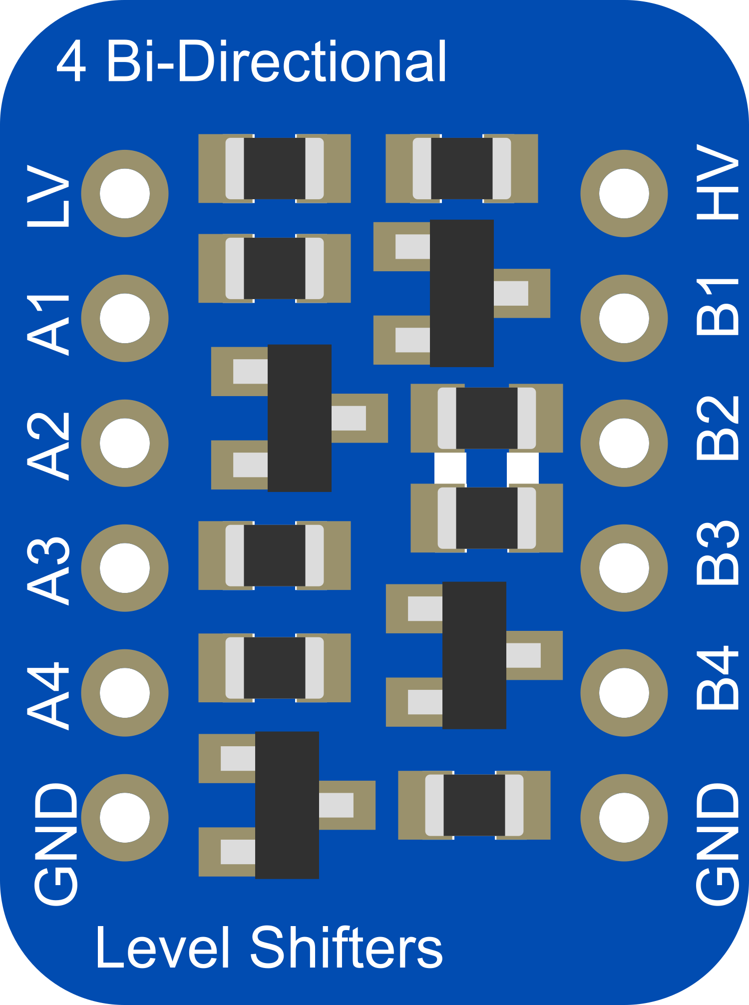
Pin Configuration and Descriptions

Pin Name Description
HV High voltage (5V) supply input
LV Low voltage (3.3V) supply input
GND Ground connection
HV1 - HV4 High voltage (5V) logic level inputs/outputs
LV1 - LV4 Low voltage (3.3V) logic level inputs/outputs

Usage Instructions

How to Use the Component in a Circuit

  1. Power Connections:

    • Connect the HV pin to the higher voltage level (e.g., 5V).
    • Connect the LV pin to the lower voltage level (e.g., 3.3V).
    • Connect the GND pin to the common ground of both systems.
  2. Signal Connections:

    • Connect the high voltage (5V) logic signals to HV1 to HV4.
    • Connect the corresponding low voltage (3.3V) logic signals to LV1 to LV4.
  3. I2C Communication:

    • For I2C communication, connect SDA and SCL lines from the 5V system to the HV side channels.
    • Connect the corresponding SDA and SCL lines from the 3.3V system to the LV side channels.

Important Considerations and Best Practices

  • Ensure that the power supply is stable and within the specified voltage range.
  • Do not exceed the maximum baud rate supported by the converter.
  • Avoid running high-speed signals through the level converter as it may not perform well with frequencies higher than I2C fast mode.
  • Always connect the ground pin first before making any other connections to prevent potential damage.

Example Code for Arduino UNO

#include <Wire.h>

void setup() {
  Wire.begin(); // join i2c bus
  Serial.begin(9600); // start serial for output
}

void loop() {
  Wire.requestFrom(0x3C, 6); // request 6 bytes from slave device #0x3C

  while (Wire.available()) { // slave may send less than requested
    char c = Wire.read(); // receive a byte as character
    Serial.print(c); // print the character
  }

  delay(500);
}

Troubleshooting and FAQs

Common Issues

  • No Signal Conversion:

    • Check if the power supply is connected correctly and the ground is common to both systems.
    • Ensure that the pins are not swapped between the HV and LV sides.
  • Device Not Recognized:

    • Verify that the I2C address is correct and the device is properly connected to the SDA and SCL lines.

Solutions and Tips for Troubleshooting

  • If you encounter issues with I2C communication, use pull-up resistors on the SDA and SCL lines appropriate for the voltage level you are working with.
  • Use a multimeter to check the continuity and voltage levels on the HV and LV sides to ensure proper operation.
  • If the logic level converter is not functioning, it may be damaged due to a voltage spike or incorrect connection. Replace the component if necessary.

FAQs

Q: Can this converter be used with SPI or UART? A: While it is designed for I2C, it may work with other protocols like SPI or UART at low speeds. However, it is not guaranteed and should be tested thoroughly.

Q: Is this converter bidirectional on all channels? A: Yes, all four channels are bidirectional and can be used for voltage stepping in both directions.

Q: What is the maximum current this converter can handle? A: The converter is designed for low-power signals and is not intended for high current applications. It is recommended to keep the current below 10mA per channel.