How to Use EMG: Examples, Pinouts, and Specs
Introduction
An Electromyography (EMG) device measures the electrical activity produced by skeletal muscles. It detects and records the electrical signals generated during muscle contraction and relaxation. EMG devices are widely used in medical diagnostics, rehabilitation, and research to assess muscle function, detect neuromuscular disorders, and study biomechanics. Additionally, EMG sensors are increasingly used in robotics, prosthetics, and human-computer interaction systems for gesture recognition and control.
Explore Projects Built with EMG

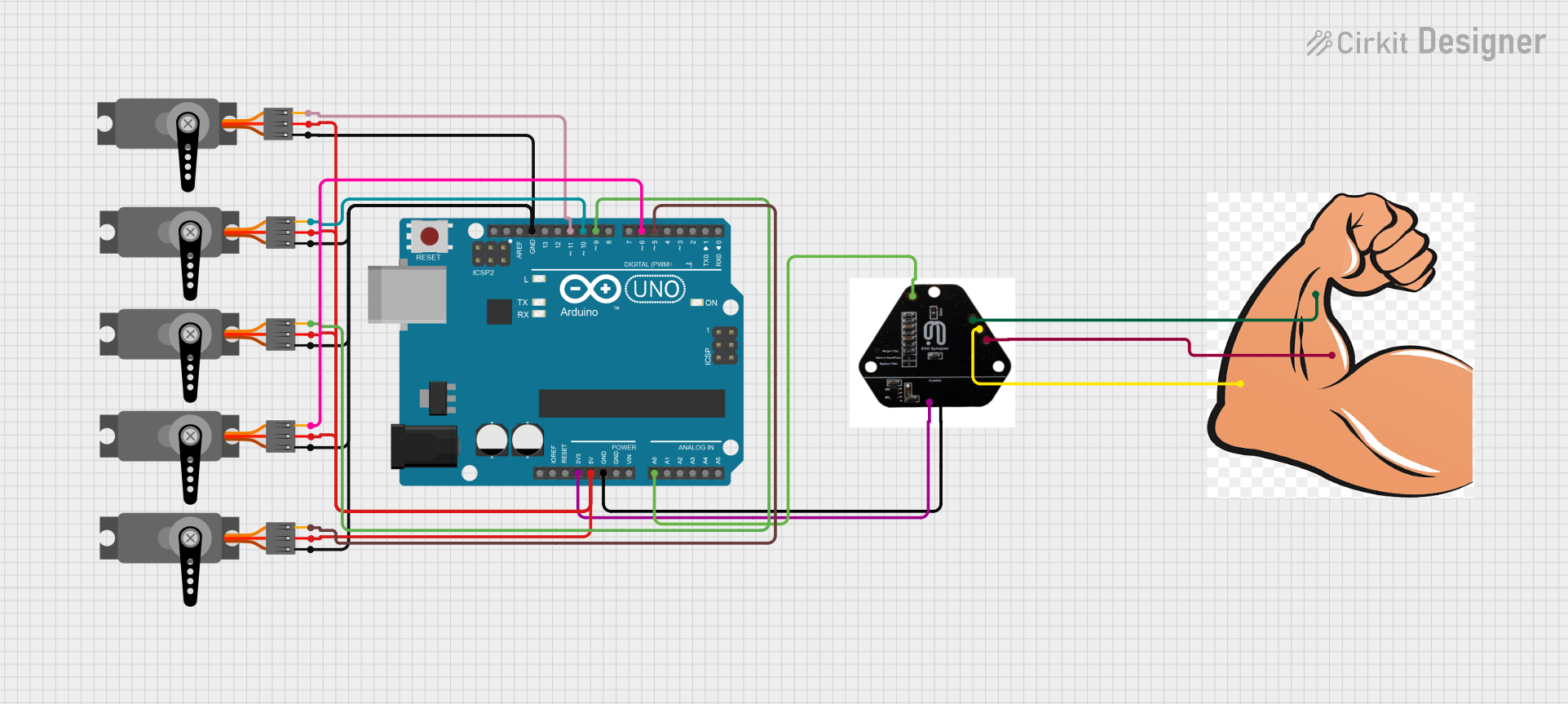
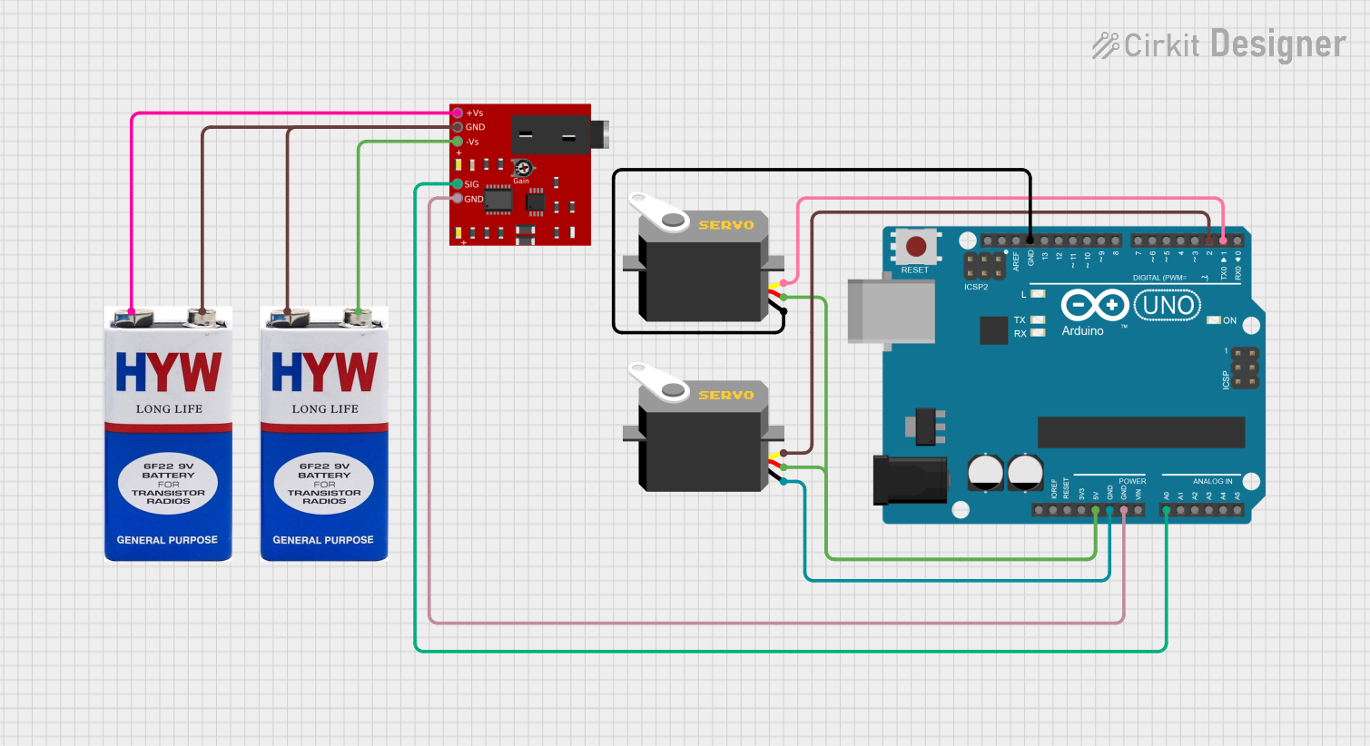
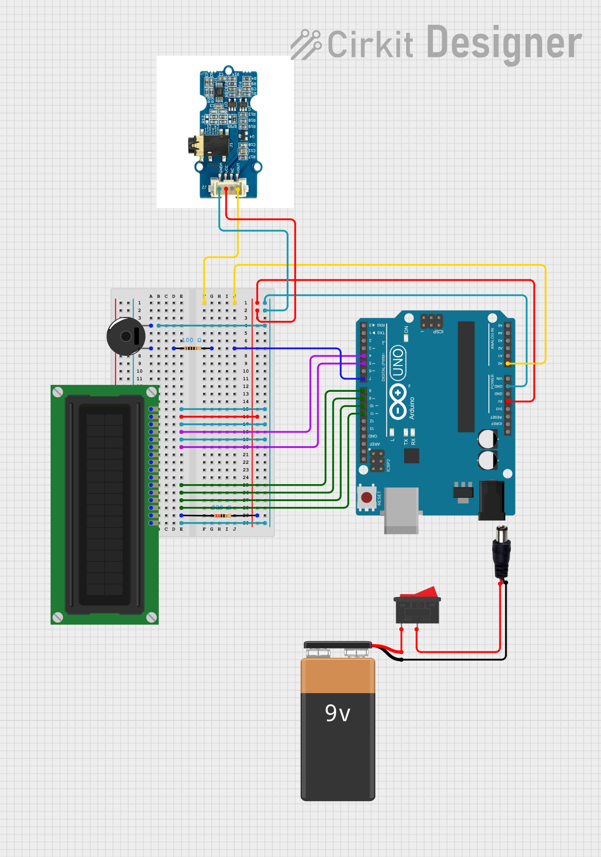
Explore Projects Built with EMG
Common Applications and Use Cases
- Medical diagnostics for neuromuscular disorders (e.g., ALS, myopathy)
- Rehabilitation and physical therapy
- Biomechanics and movement analysis
- Robotics and prosthetics control
- Gesture recognition in human-computer interaction
- Sports science and performance monitoring
Technical Specifications
Below are the general technical specifications for a typical EMG sensor module:
| Parameter | Value |
|---|---|
| Operating Voltage | 3.3V to 5V DC |
| Operating Current | ~10mA |
| Output Signal Range | 0V to 3.3V (analog signal) |
| Frequency Response | 20Hz to 500Hz |
| Gain | Adjustable (typically 100x to 1000x) |
| Input Impedance | >10MΩ |
| Electrode Type | Disposable or reusable surface electrodes |
| Output Type | Analog voltage proportional to muscle activity |
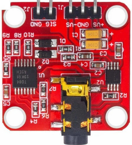
Pin Configuration and Descriptions
The EMG sensor module typically has the following pin configuration:
| Pin Name | Description |
|---|---|
| VCC | Power supply input (3.3V to 5V DC) |
| GND | Ground connection |
| SIG | Analog output signal (proportional to muscle activity) |
Usage Instructions
How to Use the EMG Sensor in a Circuit
- Connect the Power Supply:
- Connect the
VCCpin to a 3.3V or 5V DC power source. - Connect the
GNDpin to the ground of the power source.
- Connect the
- Attach Electrodes:
- Place the surface electrodes on the target muscle group. Ensure the skin is clean and dry for optimal signal quality.
- Connect the electrode cables to the EMG sensor module.
- Read the Signal:
- Connect the
SIGpin to an analog input pin of a microcontroller (e.g., Arduino UNO). - The output signal is an analog voltage that varies with muscle activity. Use an oscilloscope or microcontroller to visualize or process the signal.
- Connect the
Important Considerations and Best Practices
- Electrode Placement: Proper placement of electrodes is critical for accurate signal acquisition. Place the electrodes along the muscle fibers, avoiding bony areas.
- Signal Noise: EMG signals are susceptible to noise. Minimize noise by ensuring good electrode contact, using shielded cables, and avoiding electrical interference.
- Amplification: The raw EMG signal is weak and requires amplification. Most EMG modules include a built-in amplifier with adjustable gain.
- Filtering: Use appropriate filters (e.g., band-pass filters) to remove unwanted noise and artifacts from the signal.
Example: Connecting EMG Sensor to Arduino UNO
Below is an example of how to connect and read data from an EMG sensor using an Arduino UNO:
// Define the analog pin connected to the EMG sensor's SIG pin
const int emgPin = A0;

void setup() {
  // Initialize serial communication for debugging
  Serial.begin(9600);
}

void loop() {
  // Read the analog value from the EMG sensor
  int emgValue = analogRead(emgPin);

  // Print the EMG value to the Serial Monitor
  Serial.print("EMG Signal: ");
  Serial.println(emgValue);

  // Add a small delay to stabilize readings
  delay(10);
}
Notes:
- The
emgValuewill range from 0 to 1023 (10-bit ADC resolution on Arduino UNO). - Use the Serial Plotter in the Arduino IDE to visualize the EMG signal in real-time.
Troubleshooting and FAQs
Common Issues and Solutions
No Signal or Weak Signal:
- Ensure the electrodes are properly placed and have good contact with the skin.
- Verify that the power supply voltage is within the specified range.
- Check the electrode cables for damage or loose connections.
Excessive Noise in the Signal:
- Use shielded cables to reduce electrical interference.
- Ensure the skin is clean and free of oils or lotions.
- Place the sensor and cables away from high-power electrical devices.
Signal Saturation:
- Reduce the gain setting on the EMG module if the output signal is clipping.
- Verify that the electrodes are not placed too close to each other.
Inconsistent Readings:
- Ensure the electrodes are securely attached and not moving during muscle activity.
- Check for loose connections in the circuit.
FAQs
Q: Can I use the EMG sensor with a 3.3V microcontroller?
A: Yes, most EMG sensors are compatible with 3.3V and 5V systems. Ensure the output signal range matches the ADC input range of your microcontroller.
Q: How do I clean reusable electrodes?
A: Use a soft cloth dampened with alcohol or saline solution to clean reusable electrodes. Avoid using abrasive materials.
Q: Can I use the EMG sensor for real-time control of a robotic arm?
A: Yes, EMG sensors are commonly used for real-time control in robotics. However, you may need additional signal processing to extract meaningful control signals.
Q: What is the typical lifespan of disposable electrodes?
A: Disposable electrodes are designed for single use. Reusing them may degrade signal quality and increase noise.
By following this documentation, you can effectively integrate and utilize an EMG sensor in your projects for various applications.