How to Use ESP 32 WIFI KIT V3: Examples, Pinouts, and Specs
Introduction
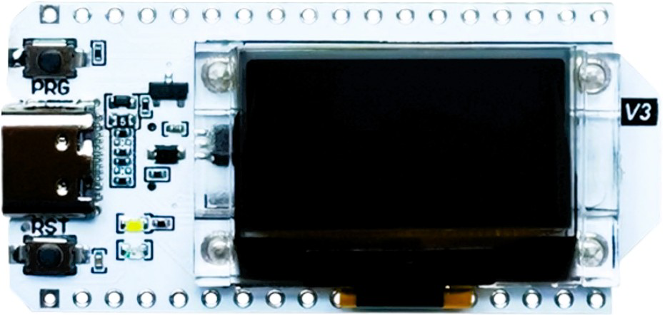
The ESP 32 WIFI KIT V3 by HELTEC is a versatile microcontroller development board designed for IoT applications. It features built-in Wi-Fi and Bluetooth capabilities, making it ideal for projects requiring wireless communication. With its compact design and integrated OLED display, the ESP 32 WIFI KIT V3 is perfect for prototyping and deploying smart devices, home automation systems, and other connected solutions.
Explore Projects Built with ESP 32 WIFI KIT V3


Explore Projects Built with ESP 32 WIFI KIT V3
Common Applications and Use Cases
- IoT (Internet of Things) devices
- Home automation systems
- Wireless sensor networks
- Smart appliances
- Wearable technology
- Prototyping and educational projects
Technical Specifications
The following table outlines the key technical specifications of the ESP 32 WIFI KIT V3:
| Specification | Details |
|---|---|
| Manufacturer | HELTEC |
| Part ID | ESP 32 |
| Microcontroller | ESP32-D0WDQ6 |
| Wireless Connectivity | Wi-Fi 802.11 b/g/n, Bluetooth 4.2 (Classic and BLE) |
| Operating Voltage | 3.3V |
| Input Voltage Range | 5V (via USB) |
| Flash Memory | 4MB |
| SRAM | 520KB |
| GPIO Pins | 28 |
| Communication Interfaces | UART, SPI, I2C, I2S, CAN, PWM |
| Integrated Display | 0.96-inch OLED (128x64 resolution) |
| Power Consumption | Ultra-low power consumption in deep sleep mode (as low as 10 µA) |
| Dimensions | 41mm x 28mm |
Pin Configuration and Descriptions
The ESP 32 WIFI KIT V3 has a total of 28 GPIO pins, each with multiple functions. Below is a summary of the pin configuration:
| Pin | Function | Description |
|---|---|---|
| 3V3 | Power | 3.3V power output |
| GND | Ground | Ground connection |
| EN | Enable | Enables the chip when pulled high |
| GPIO0 | Input/Output, Boot Mode | Used for boot mode selection during programming |
| GPIO1 | UART TX | UART transmit pin |
| GPIO3 | UART RX | UART receive pin |
| GPIO4 | Input/Output, PWM, ADC | General-purpose I/O with PWM and ADC capabilities |
| GPIO5 | Input/Output, PWM, ADC | General-purpose I/O with PWM and ADC capabilities |
| GPIO16 | Input/Output | General-purpose I/O |
| GPIO17 | Input/Output | General-purpose I/O |
| GPIO21 | I2C SDA | I2C data line |
| GPIO22 | I2C SCL | I2C clock line |
| GPIO23 | SPI MOSI | SPI Master Out Slave In |
| GPIO18 | SPI SCK | SPI clock |
| GPIO19 | SPI MISO | SPI Master In Slave Out |
| GPIO25 | DAC1 | Digital-to-Analog Converter channel 1 |
| GPIO26 | DAC2 | Digital-to-Analog Converter channel 2 |
| GPIO34 | ADC | Analog-to-Digital Converter input |
| GPIO35 | ADC | Analog-to-Digital Converter input |
Note: Some pins have multiple functions. Refer to the ESP32 datasheet for advanced configurations.
Usage Instructions
How to Use the ESP 32 WIFI KIT V3 in a Circuit
Powering the Board:
- Connect the board to a computer or USB power source using a micro-USB cable. The onboard voltage regulator will convert the 5V input to the required 3.3V operating voltage.
Programming the Board:
- Install the Arduino IDE and add the ESP32 board support package.
- Select the correct board (
Heltec ESP32) and port in the Arduino IDE. - Write or upload your code to the board via the USB connection.
Connecting Peripherals:
- Use the GPIO pins to connect sensors, actuators, or other peripherals.
- Ensure that the voltage levels of connected devices are compatible with the 3.3V logic of the ESP32.
Using the OLED Display:
- The integrated OLED display can be controlled using the I2C protocol. The default I2C address is
0x3C.
- The integrated OLED display can be controlled using the I2C protocol. The default I2C address is
Important Considerations and Best Practices
- Voltage Levels: Avoid applying voltages higher than 3.3V to the GPIO pins to prevent damage.
- Deep Sleep Mode: Use deep sleep mode to conserve power in battery-powered applications.
- Antenna Placement: Ensure the onboard antenna is not obstructed by metal objects to maintain optimal wireless performance.
- Boot Mode: Hold down the
BOOTbutton while pressing theENbutton to enter programming mode.
Example Code for Arduino UNO
Below is an example of how to use the ESP 32 WIFI KIT V3 to display text on the OLED screen:
#include <Wire.h>
#include <Adafruit_GFX.h>
#include <Adafruit_SSD1306.h>

// Define OLED display width and height
#define SCREEN_WIDTH 128
#define SCREEN_HEIGHT 64

// Create an OLED display object
Adafruit_SSD1306 display(SCREEN_WIDTH, SCREEN_HEIGHT, &Wire, -1);

void setup() {
  // Initialize serial communication for debugging
  Serial.begin(115200);

  // Initialize the OLED display
  if (!display.begin(SSD1306_I2C_ADDRESS, 0x3C)) {
    Serial.println(F("SSD1306 allocation failed"));
    while (true); // Halt execution if display initialization fails
  }

  // Clear the display buffer
  display.clearDisplay();

  // Display a message
  display.setTextSize(1); // Set text size
  display.setTextColor(SSD1306_WHITE); // Set text color
  display.setCursor(0, 0); // Set cursor position
  display.println(F("Hello, ESP32!")); // Print message
  display.display(); // Update the display
}

void loop() {
  // Nothing to do here
}
Note: Install the
Adafruit GFXandAdafruit SSD1306libraries in the Arduino IDE before running the code.
Troubleshooting and FAQs
Common Issues and Solutions
The board is not detected by the computer:
- Ensure the USB cable is functional and supports data transfer.
- Install the correct USB-to-serial driver for the ESP32.
OLED display does not work:
- Verify the I2C address (
0x3C) and connections. - Ensure the
Adafruit SSD1306library is installed and properly configured.
- Verify the I2C address (
Wi-Fi connection fails:
- Check the SSID and password in your code.
- Ensure the Wi-Fi network is within range and operational.
Program upload fails:
- Hold the
BOOTbutton while uploading the code. - Verify the correct board and port are selected in the Arduino IDE.
- Hold the
FAQs
Can I power the board with a battery?
Yes, the board can be powered using a 3.7V LiPo battery connected to the JST connector.What is the maximum range of the Wi-Fi module?
The Wi-Fi range depends on environmental factors but typically extends up to 100 meters in open spaces.Can I use the ESP 32 WIFI KIT V3 with MicroPython?
Yes, the board supports MicroPython. Flash the MicroPython firmware to get started.Is the board compatible with Arduino libraries?
Yes, the ESP32 is compatible with most Arduino libraries, making it easy to integrate into existing projects.