
How to Use ESP32: Examples, Pinouts, and Specs
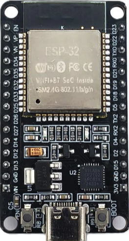
 Design with ESP32 in Cirkit Designer
Introduction
The ESP32, manufactured by Espressif Systems (Shanghai) Co., Ltd, is a low-cost, low-power system on a chip (SoC) with integrated Wi-Fi and Bluetooth capabilities. It is widely used in Internet of Things (IoT) applications due to its versatility, high performance, and robust connectivity features. The ESP32 DEVKITV1 is a development board based on the ESP32 SoC, designed to simplify prototyping and development.
Explore Projects Built with ESP32
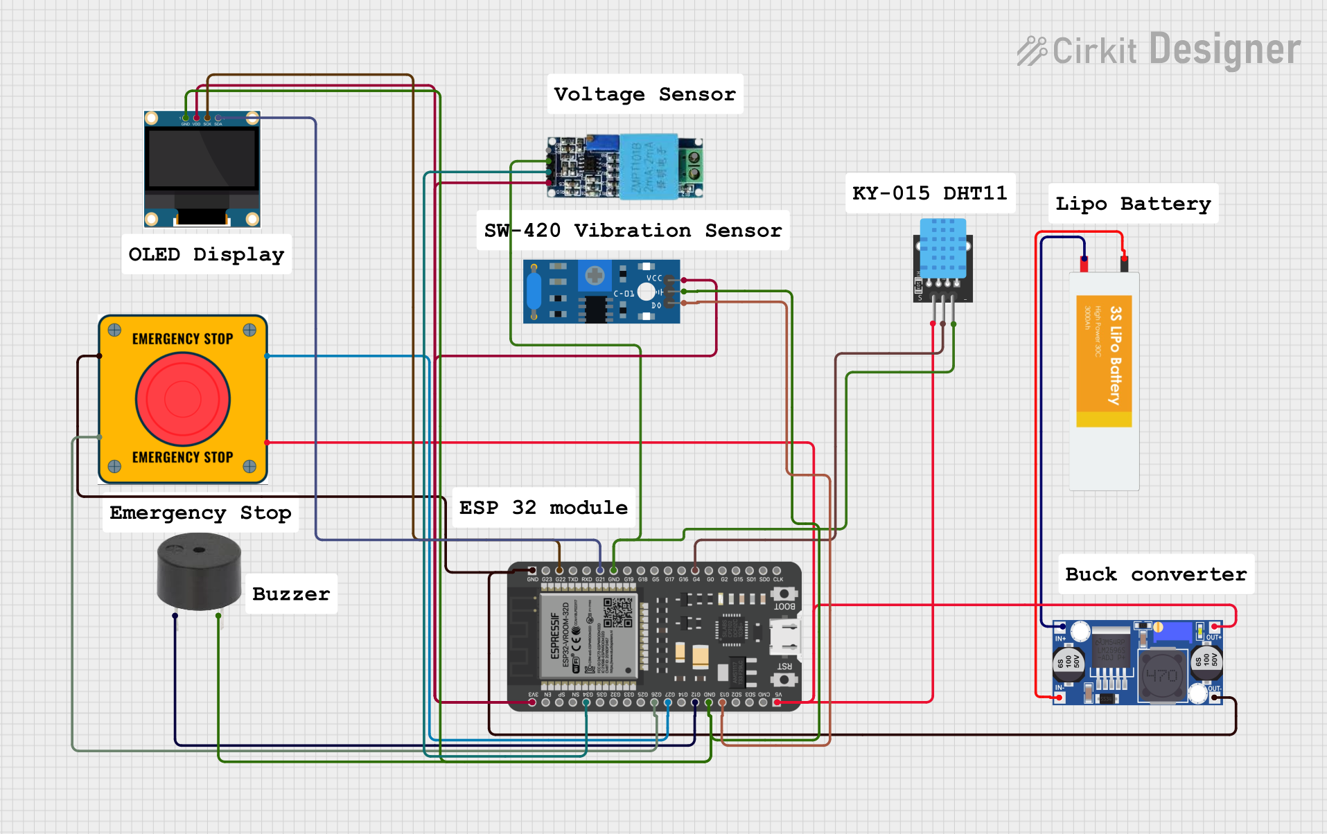 Open Project in Cirkit Designer
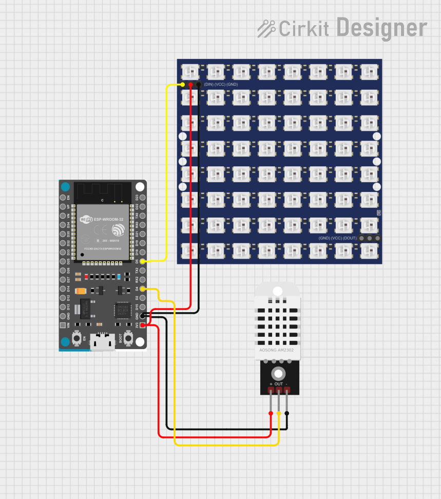 Open Project in Cirkit Designer
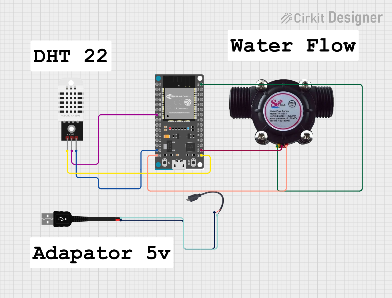 Open Project in Cirkit Designer
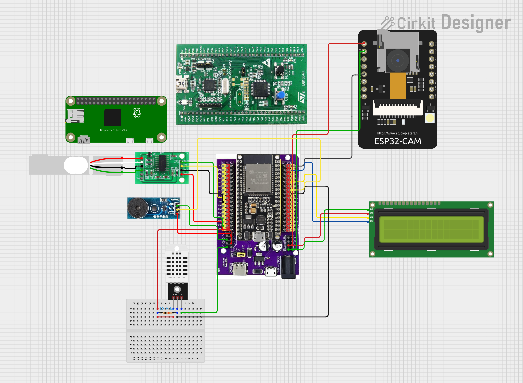 Open Project in Cirkit Designer
Explore Projects Built with ESP32
Open Project in Cirkit DesignerOpen Project in Cirkit DesignerOpen Project in Cirkit DesignerOpen Project in Cirkit DesignerCommon Applications and Use Cases
- IoT devices and smart home automation
- Wireless sensor networks
- Wearable electronics
- Industrial automation
- Robotics and drones
- Audio streaming and Bluetooth applications
Technical Specifications
Key Technical Details
| Parameter | Specification |
|---|---|
| Manufacturer | Espressif Systems (Shanghai) Co., Ltd |
| Part ID | DEVKITV1 |
| Microcontroller | Tensilica Xtensa LX6 dual-core or single-core |
| Clock Speed | Up to 240 MHz |
| Flash Memory | 4 MB (varies by model) |
| SRAM | 520 KB |
| Connectivity | Wi-Fi 802.11 b/g/n, Bluetooth v4.2 + BLE |
| Operating Voltage | 3.3V |
| Input Voltage (VIN) | 5V (via USB or external power supply) |
| GPIO Pins | 34 (multipurpose, including ADC, DAC, PWM, etc.) |
| ADC Channels | 18 (12-bit resolution) |
| DAC Channels | 2 (8-bit resolution) |
| Power Consumption | Ultra-low power (varies by mode) |
| Operating Temperature | -40°C to +85°C |
Pin Configuration and Descriptions
The ESP32 DEVKITV1 has a total of 38 pins. Below is a summary of the key pins and their functions:
| Pin Name | Function | Description |
|---|---|---|
| VIN | Power Input | Accepts 5V input to power the board. |
| 3V3 | Power Output | Provides 3.3V output for external components. |
| GND | Ground | Common ground for the circuit. |
| EN | Enable | Enables or disables the chip (active high). |
| GPIO0 | Boot Mode Selection | Used for flashing firmware (connect to GND during boot). |
| GPIO2 | General Purpose I/O | Can be used as a standard GPIO pin. |
| GPIO12 | ADC2 Channel 5 | Analog input or digital I/O. |
| GPIO13 | ADC2 Channel 4, Touch Sensor 4 | Analog input, digital I/O, or touch input. |
| GPIO15 | ADC2 Channel 3, Touch Sensor 3 | Analog input, digital I/O, or touch input. |
| GPIO16 | General Purpose I/O | Can be used as a standard GPIO pin. |
| GPIO17 | General Purpose I/O | Can be used as a standard GPIO pin. |
| TXD0 | UART0 Transmit | Serial communication transmit pin. |
| RXD0 | UART0 Receive | Serial communication receive pin. |
| ADC1 | Analog-to-Digital Converter | 12-bit ADC with multiple channels. |
| DAC1 | Digital-to-Analog Converter | 8-bit DAC output. |
Note: Not all GPIO pins are available for general use, as some are reserved for internal functions. Refer to the ESP32 datasheet for detailed pin multiplexing information.
Usage Instructions
How to Use the ESP32 in a Circuit
Powering the ESP32:
- Connect the VIN pin to a 5V power source or use the micro-USB port for power and programming.
- Ensure the GND pin is connected to the ground of your circuit.
Programming the ESP32:
- Install the Arduino IDE and add the ESP32 board support package.
- Connect the ESP32 to your computer via a USB cable.
- Select the correct board (
ESP32 Dev Module) and port in the Arduino IDE. - Write or upload your code to the ESP32.
Connecting Peripherals:
- Use GPIO pins for digital I/O, ADC pins for analog input, and DAC pins for analog output.
- Ensure external components operate at 3.3V logic levels to avoid damaging the ESP32.
Wi-Fi and Bluetooth Setup:
- Use the built-in libraries (
WiFi.handBluetoothSerial.h) to configure wireless communication.
- Use the built-in libraries (
Important Considerations and Best Practices
- Voltage Levels: The ESP32 operates at 3.3V. Avoid applying 5V directly to GPIO pins.
- Boot Mode: To flash firmware, connect GPIO0 to GND during boot.
- Power Supply: Use a stable power source to avoid unexpected resets or instability.
- Heat Management: The ESP32 may heat up during operation. Ensure proper ventilation if used in enclosed spaces.
Example Code: Blinking an LED
Below is an example of how to blink an LED connected to GPIO2 using the Arduino IDE:
// Define the GPIO pin where the LED is connected
#define LED_PIN 2

void setup() {
  pinMode(LED_PIN, OUTPUT); // Set GPIO2 as an output pin
}

void loop() {
  digitalWrite(LED_PIN, HIGH); // Turn the LED on
  delay(1000);                 // Wait for 1 second
  digitalWrite(LED_PIN, LOW);  // Turn the LED off
  delay(1000);                 // Wait for 1 second
}
Example Code: Connecting to Wi-Fi
Below is an example of how to connect the ESP32 to a Wi-Fi network:
#include <WiFi.h> // Include the Wi-Fi library

// Replace with your network credentials
const char* ssid = "Your_SSID";
const char* password = "Your_PASSWORD";

void setup() {
  Serial.begin(115200); // Start the serial communication
  WiFi.begin(ssid, password); // Connect to the Wi-Fi network

  // Wait for the connection to establish
  while (WiFi.status() != WL_CONNECTED) {
    delay(1000);
    Serial.println("Connecting to Wi-Fi...");
  }

  Serial.println("Connected to Wi-Fi!");
}

void loop() {
  // Add your main code here
}
Troubleshooting and FAQs
Common Issues and Solutions
ESP32 Not Detected by Computer:
- Ensure the USB cable is functional and supports data transfer.
- Install the correct USB-to-serial driver for your operating system.
Wi-Fi Connection Fails:
- Double-check the SSID and password.
- Ensure the Wi-Fi network is within range and operational.
Random Resets or Instability:
- Verify the power supply is stable and capable of providing sufficient current.
- Avoid using GPIO pins reserved for internal functions.
GPIO Pin Not Working:
- Check if the pin is being used for another function (e.g., boot mode).
- Ensure the pin is not damaged or overloaded.
FAQs
Q: Can the ESP32 operate on battery power?
A: Yes, the ESP32 can be powered by a battery. Use a 3.7V LiPo battery with a voltage regulator to provide 3.3V.
Q: How do I reset the ESP32?
A: Press the onboard reset button or toggle the EN pin.
Q: Can I use the ESP32 with 5V logic devices?
A: No, the ESP32 operates at 3.3V logic levels. Use a level shifter for compatibility with 5V devices.
Q: How do I update the firmware?
A: Use the Arduino IDE or Espressif's esptool.py to flash new firmware via the USB connection.