How to Use AS3935: Examples, Pinouts, and Specs
Introduction
The AS3935 is a lightning sensor IC manufactured by Energy, with the part ID 000. This highly sensitive component is designed to detect lightning strikes and provide an output signal indicating the presence of lightning activity. It features a low-power design, making it ideal for battery-operated devices. The AS3935 can communicate with microcontrollers via I2C or SPI interfaces, offering flexibility in integration.
Explore Projects Built with AS3935
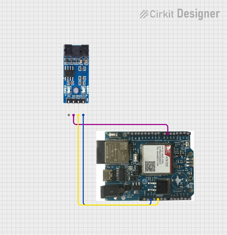

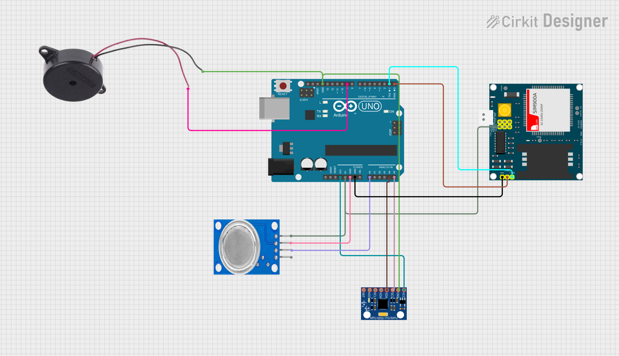

Explore Projects Built with AS3935
Common Applications and Use Cases
- Weather monitoring systems
- Outdoor safety equipment
- IoT devices for environmental sensing
- Portable lightning detection devices
- Smart home automation systems
Technical Specifications
The AS3935 is a robust and versatile component with the following key specifications:
| Parameter | Value |
|---|---|
| Operating Voltage | 2.4V to 5.5V |
| Current Consumption | 60 µA (typical in listening mode) |
| Communication Interfaces | I2C, SPI |
| Lightning Detection Range | Up to 40 km |
| Operating Temperature Range | -40°C to +85°C |
| Package Type | 16-pin MLPQ (4x4 mm) |
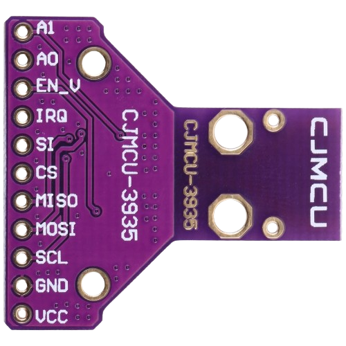
Pin Configuration and Descriptions
The AS3935 has a 16-pin configuration. Below is a detailed description of each pin:
| Pin Number | Pin Name | Description |
|---|---|---|
| 1 | VDD | Power supply input (2.4V to 5.5V). |
| 2 | GND | Ground connection. |
| 3 | SCL | I2C clock line (or SPI clock in SPI mode). |
| 4 | SDA | I2C data line (or SPI MOSI in SPI mode). |
| 5 | IRQ | Interrupt output pin, signals lightning detection or other events. |
| 6 | CS | Chip select for SPI communication (connect to GND for I2C mode). |
| 7 | MISO | SPI data output (not used in I2C mode). |
| 8 | A0 | I2C address selection pin (connect to GND or VDD to set address). |
| 9 | TUN_CAP | External tuning capacitor connection for antenna matching. |
| 10 | ANT | Antenna input for lightning detection. |
| 11-16 | NC | No connection (leave unconnected). |
Usage Instructions
How to Use the AS3935 in a Circuit
- Power Supply: Connect the VDD pin to a stable power source (2.4V to 5.5V) and the GND pin to ground.
- Communication Interface:
- For I2C mode, connect the SCL and SDA pins to the corresponding I2C lines of your microcontroller. Pull-up resistors (typically 4.7kΩ) are required on these lines.
- For SPI mode, connect the SCL, MISO, and CS pins to the corresponding SPI lines of your microcontroller.
- Interrupt Handling: Connect the IRQ pin to a GPIO pin on your microcontroller to handle lightning detection interrupts.
- Antenna Tuning: Attach an external antenna to the ANT pin and connect a tuning capacitor to the TUN_CAP pin for optimal performance.
- Address Selection: If using I2C, set the I2C address by connecting the A0 pin to either GND or VDD.
Important Considerations and Best Practices
- Antenna Placement: Ensure the antenna is placed away from noise sources to avoid false detections.
- Tuning Capacitor: Properly tune the capacitor value to match the antenna for accurate lightning detection.
- Interrupt Handling: Implement a robust interrupt service routine (ISR) to process lightning detection events.
- Power Management: Use the low-power listening mode to conserve energy in battery-operated devices.
Example Code for Arduino UNO
Below is an example of how to interface the AS3935 with an Arduino UNO using the I2C interface:
#include <Wire.h>

// AS3935 I2C address (set by A0 pin connection)
#define AS3935_I2C_ADDRESS 0x03

// Pin connected to the IRQ pin of AS3935
#define IRQ_PIN 2

void setup() {
  // Initialize serial communication for debugging
  Serial.begin(9600);

  // Initialize I2C communication
  Wire.begin();

  // Configure IRQ pin as input
  pinMode(IRQ_PIN, INPUT);

  // Attach interrupt to handle lightning detection
  attachInterrupt(digitalPinToInterrupt(IRQ_PIN), lightningDetected, RISING);

  // Initialize AS3935 (example: write to a configuration register)
  Wire.beginTransmission(AS3935_I2C_ADDRESS);
  Wire.write(0x00); // Register address
  Wire.write(0x96); // Example configuration value
  Wire.endTransmission();

  Serial.println("AS3935 initialized.");
}

void loop() {
  // Main loop can handle other tasks
  delay(1000);
}

// Interrupt service routine for lightning detection
void lightningDetected() {
  Serial.println("Lightning detected!");
  // Additional processing can be added here
}
Troubleshooting and FAQs
Common Issues and Solutions
No Lightning Detection:
- Ensure the antenna is properly connected and tuned with the correct capacitor value.
- Verify that the AS3935 is powered correctly and the communication interface is configured properly.
False Detections:
- Check for nearby sources of electromagnetic interference (EMI) and relocate the sensor if necessary.
- Ensure proper grounding and shielding of the circuit.
I2C/SPI Communication Failure:
- Verify the wiring and ensure pull-up resistors are used for I2C lines.
- Check the I2C address or SPI configuration settings.
IRQ Pin Not Triggering:
- Confirm that the IRQ pin is connected to the correct GPIO pin on the microcontroller.
- Ensure the interrupt is enabled and properly configured in the microcontroller code.
FAQs
Q: Can the AS3935 detect lightning indoors?
A: The AS3935 is designed for outdoor use and may not perform optimally indoors due to signal attenuation caused by walls and other structures.
Q: What is the maximum detection range of the AS3935?
A: The AS3935 can detect lightning strikes up to 40 km away under optimal conditions.
Q: Can I use the AS3935 with a 3.3V microcontroller?
A: Yes, the AS3935 operates within a voltage range of 2.4V to 5.5V, making it compatible with 3.3V systems.