
How to Use Packages:: Examples, Pinouts, and Specs
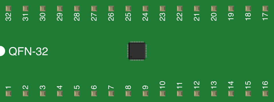
 Design with Packages: in Cirkit Designer
Introduction
Packages are protective enclosures that house electronic components, providing physical support and electrical connections while shielding them from environmental factors. They play a critical role in ensuring the reliability and performance of electronic devices by protecting sensitive components from mechanical damage, moisture, dust, and other environmental hazards. Packages also facilitate the integration of components into circuits by providing standardized pin configurations and mounting options.
Common applications of packages include:
- Housing integrated circuits (ICs) such as microcontrollers, operational amplifiers, and memory chips.
- Protecting discrete components like transistors, diodes, and resistors.
- Enabling surface-mount or through-hole mounting on printed circuit boards (PCBs).
- Ensuring thermal management and heat dissipation for high-power components.
Explore Projects Built with Packages:
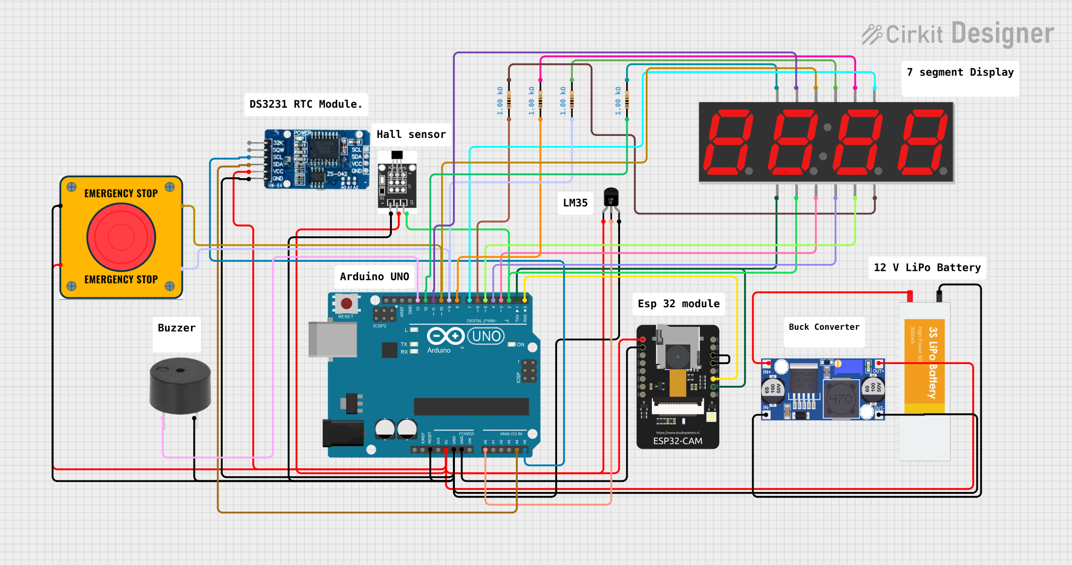 Open Project in Cirkit Designer
 Open Project in Cirkit Designer
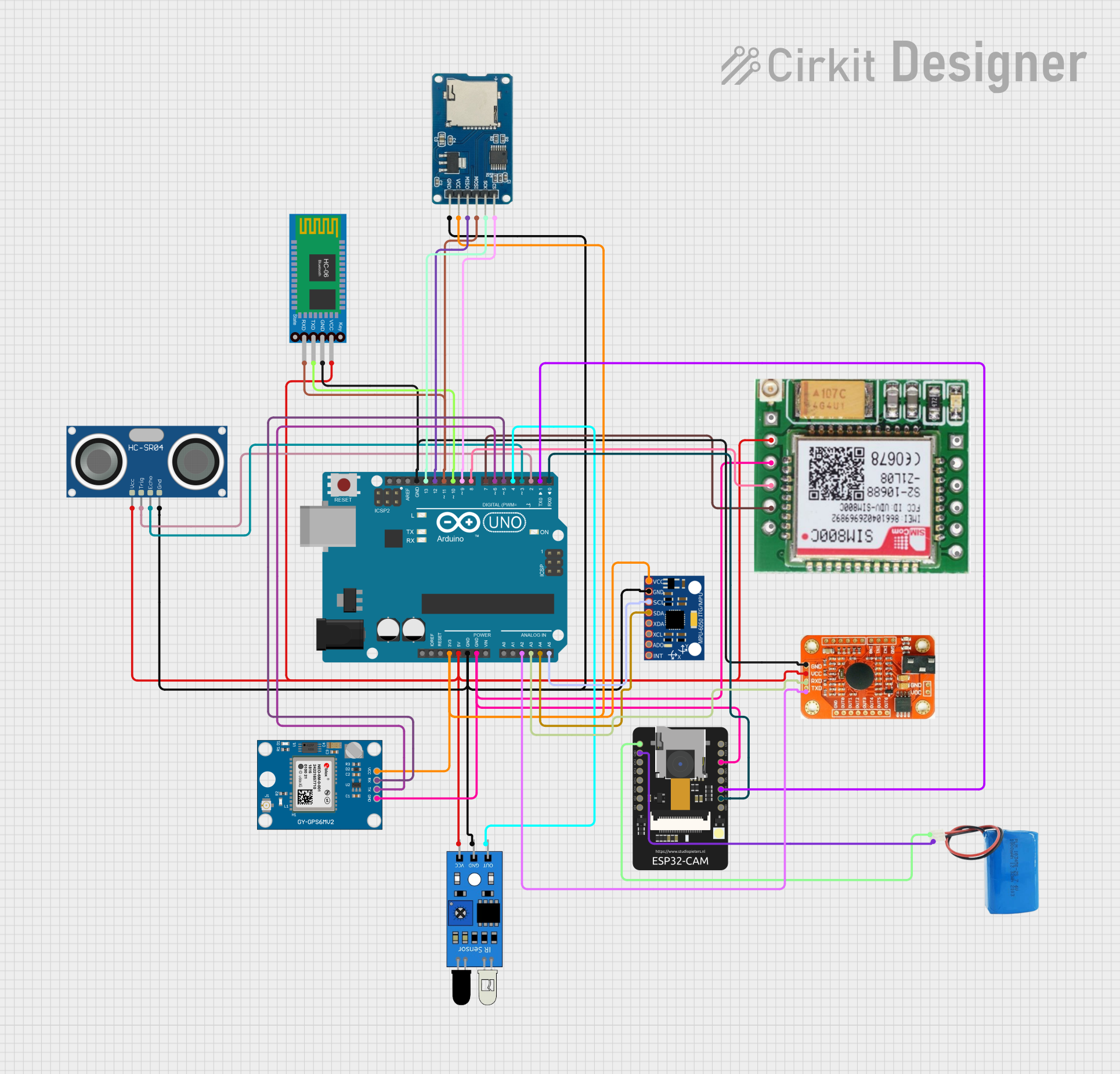 Open Project in Cirkit Designer
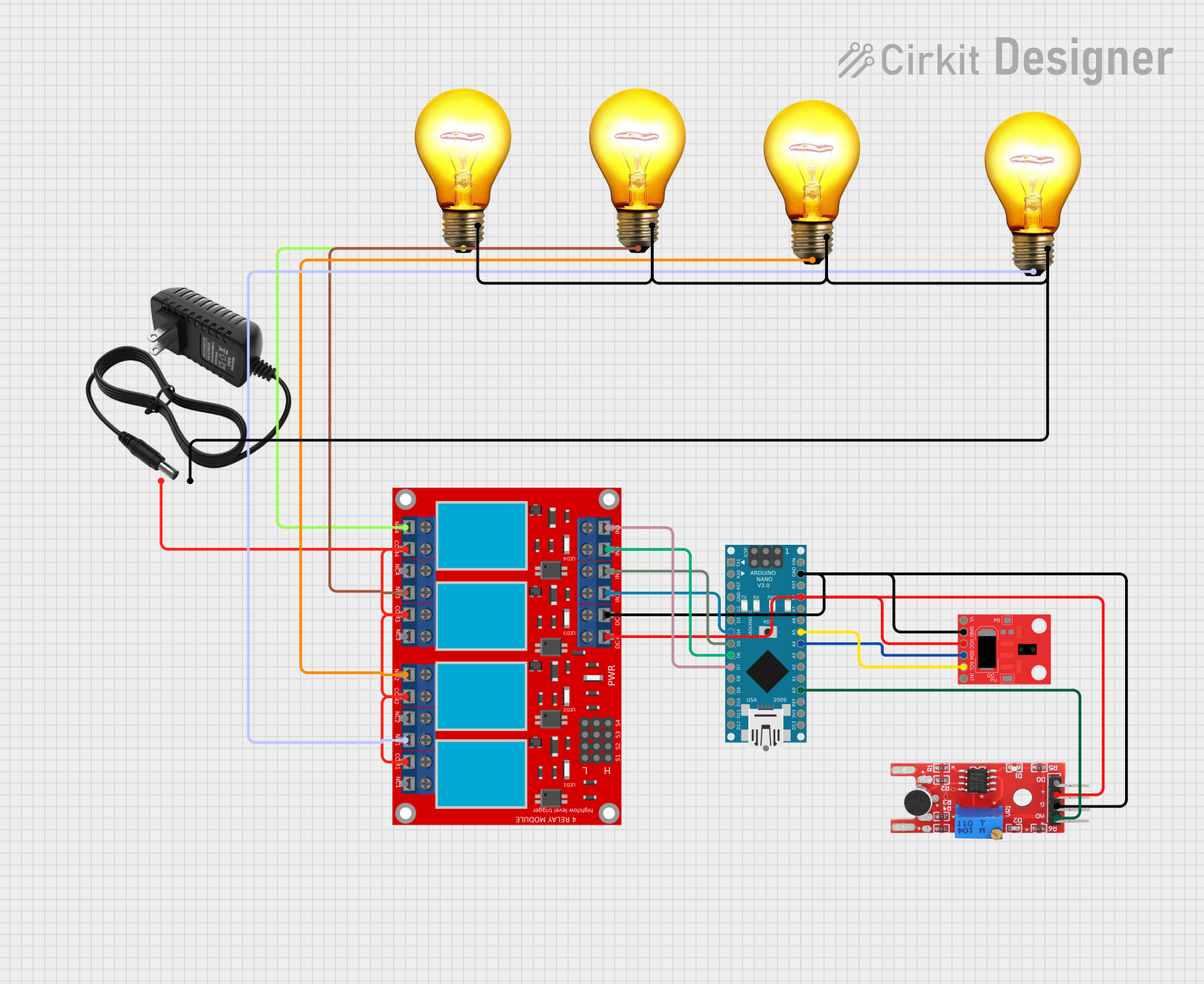 Open Project in Cirkit Designer
Explore Projects Built with Packages:
Open Project in Cirkit DesignerOpen Project in Cirkit DesignerOpen Project in Cirkit DesignerOpen Project in Cirkit DesignerTechnical Specifications
Packages come in a variety of types, each designed for specific applications and mounting methods. Below are some common package types and their key specifications:
Common Package Types
| Package Type | Description | Mounting Type | Example Components |
|---|---|---|---|
| DIP (Dual In-line Package) | Rectangular package with two parallel rows of pins for through-hole mounting. | Through-hole | Microcontrollers, ICs |
| SMD (Surface-Mount Device) | Compact package designed for surface mounting on PCBs. | Surface-mount | Resistors, capacitors, ICs |
| TO-220 | Package with a metal tab for heat dissipation, used for power components. | Through-hole | Voltage regulators, MOSFETs |
| QFP (Quad Flat Package) | Flat package with pins on all four sides for high pin-count ICs. | Surface-mount | Microprocessors, DSPs |
| BGA (Ball Grid Array) | Package with solder balls underneath for high-density connections. | Surface-mount | CPUs, GPUs, FPGAs |
Example Pin Configuration: DIP-14 Package
The DIP-14 package is commonly used for ICs such as logic gates and timers. Below is an example pin configuration for a generic DIP-14 package:
| Pin Number | Pin Name | Description |
|---|---|---|
| 1 | VCC | Power supply (positive voltage) |
| 2-7 | Input/Output | General-purpose input/output pins |
| 8 | GND | Ground (negative voltage) |
| 9-13 | Input/Output | General-purpose input/output pins |
| 14 | NC (No Connect) | Not connected internally |
Usage Instructions
How to Use Packages in a Circuit
- Identify the Package Type: Determine whether the component uses a through-hole or surface-mount package. This will dictate the PCB design and soldering method.
- Check the Pinout: Refer to the datasheet of the specific component to understand the pin configuration and ensure proper connections.
- Soldering:
- For through-hole packages, insert the pins into the PCB holes and solder them on the opposite side.
- For surface-mount packages, apply solder paste to the PCB pads, place the component, and use a reflow oven or hot air gun to solder.
- Thermal Management: For high-power packages like TO-220, attach a heatsink or use thermal paste to improve heat dissipation.
- Verify Connections: Use a multimeter to check for proper connections and ensure there are no short circuits.
Important Considerations and Best Practices
- Avoid Overheating: Excessive heat during soldering can damage the package or internal components. Use appropriate soldering tools and techniques.
- Handle with Care: Packages, especially surface-mount types, are delicate and can be damaged by rough handling or electrostatic discharge (ESD). Use ESD-safe tools and wrist straps.
- Follow Manufacturer Guidelines: Always refer to the component's datasheet for specific mounting, soldering, and operating instructions.
Example: Connecting a DIP-14 IC to an Arduino UNO
Below is an example of how to connect a DIP-14 IC (e.g., a 74HC595 shift register) to an Arduino UNO:
// Example code to control a 74HC595 shift register with an Arduino UNO
// Pins: 74HC595 (DIP-14) connected to Arduino UNO

const int dataPin = 2;  // DS (Serial Data Input) connected to Arduino pin 2
const int clockPin = 3; // SHCP (Shift Clock) connected to Arduino pin 3
const int latchPin = 4; // STCP (Storage Register Clock) connected to Arduino pin 4

void setup() {
  pinMode(dataPin, OUTPUT);  // Set data pin as output
  pinMode(clockPin, OUTPUT); // Set clock pin as output
  pinMode(latchPin, OUTPUT); // Set latch pin as output
}

void loop() {
  digitalWrite(latchPin, LOW); // Prepare to send data
  shiftOut(dataPin, clockPin, MSBFIRST, 0b10101010); // Send 8 bits of data
  digitalWrite(latchPin, HIGH); // Latch the data to output pins
  delay(1000); // Wait for 1 second
}
Troubleshooting and FAQs
Common Issues
Component Overheating:
- Cause: Insufficient heat dissipation or incorrect soldering.
- Solution: Use a heatsink for high-power packages and ensure proper soldering techniques.
Incorrect Pin Connections:
- Cause: Misinterpreting the pinout or datasheet.
- Solution: Double-check the datasheet and verify connections with a multimeter.
Soldering Defects:
- Cause: Cold solder joints or solder bridges.
- Solution: Inspect solder joints under magnification and rework if necessary.
ESD Damage:
- Cause: Handling sensitive components without ESD protection.
- Solution: Use ESD-safe tools and wear an anti-static wrist strap.
FAQs
Q: How do I identify the package type of a component?
A: The package type is usually specified in the component's datasheet. You can also identify it visually based on its shape, size, and pin configuration.
Q: Can I use a surface-mount package without a reflow oven?
A: Yes, you can use a hot air gun or soldering iron with fine tips for small-scale projects, but a reflow oven is recommended for consistent results.
Q: What is the purpose of the metal tab on a TO-220 package?
A: The metal tab is used for heat dissipation. It can be attached to a heatsink or PCB for improved thermal management.