How to Use DS3231: Examples, Pinouts, and Specs
Introduction
The DS3231 is a highly accurate real-time clock (RTC) module designed to keep track of the current time and date. It features a temperature-compensated crystal oscillator (TCXO) that ensures precise timekeeping, even under varying environmental conditions. The module communicates with microcontrollers via an I2C interface, making it easy to integrate into a wide range of projects.
Explore Projects Built with DS3231


Explore Projects Built with DS3231
Common Applications and Use Cases
- Time-stamping data in data logging systems
- Alarm clock and timer applications
- Scheduling tasks in embedded systems
- Home automation systems
- Wearable devices and portable electronics
Technical Specifications
The DS3231 offers robust performance and a variety of features. Below are its key technical specifications:
| Parameter | Value |
|---|---|
| Supply Voltage (Vcc) | 2.3V to 5.5V |
| Timekeeping Accuracy | ±2 ppm (0°C to +40°C), ±3.5 ppm (-40°C to +85°C) |
| Communication Interface | I2C (2-wire) |
| Operating Temperature Range | -40°C to +85°C |
| Backup Battery Voltage | 2.3V to 3.7V |
| Current Consumption | 1.5 µA (battery backup mode) |
| Oscillator | Built-in temperature-compensated crystal oscillator (TCXO) |
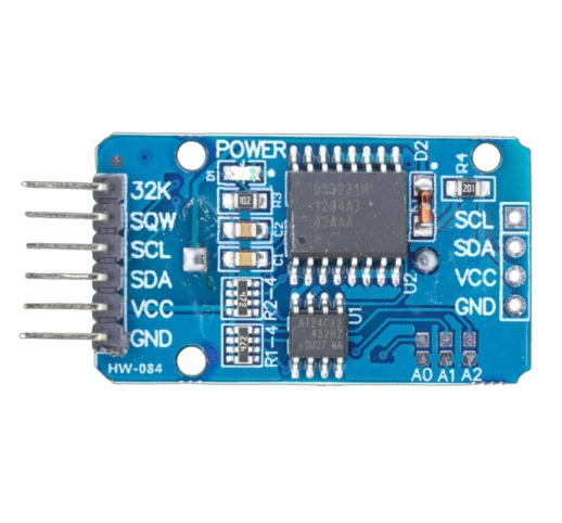
Pin Configuration and Descriptions
The DS3231 module typically has the following pinout:
| Pin | Name | Description |
|---|---|---|
| 1 | VCC | Power supply input (2.3V to 5.5V) |
| 2 | GND | Ground |
| 3 | SDA | Serial Data Line for I2C communication |
| 4 | SCL | Serial Clock Line for I2C communication |
| 5 | 32K | Optional 32.768 kHz output (can be left unconnected) |
| 6 | SQW | Square Wave/Interrupt output (programmable frequency) |
Usage Instructions
The DS3231 is straightforward to use in a circuit. Below are the steps and considerations for integrating it into your project:
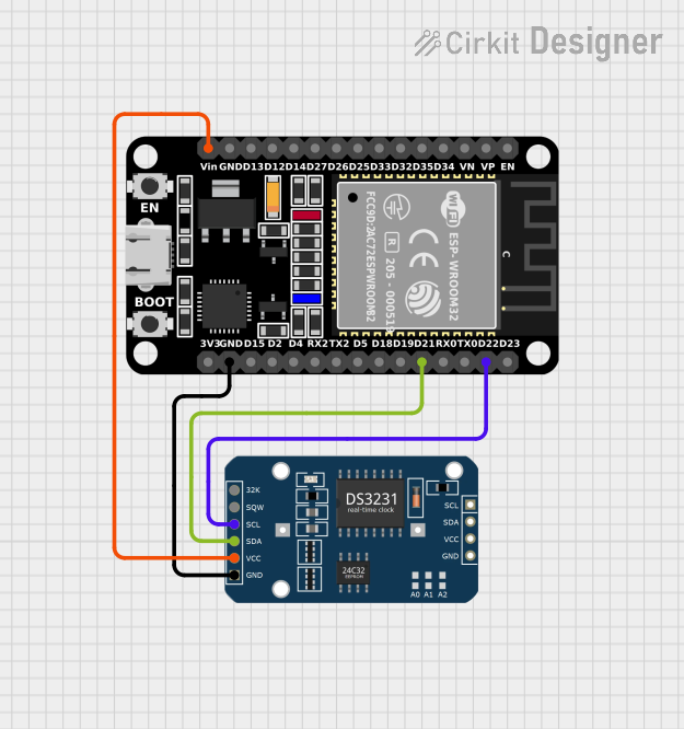
Connecting the DS3231 to a Microcontroller
- Power Supply: Connect the VCC pin to a 3.3V or 5V power source, depending on your microcontroller's logic level. Connect the GND pin to ground.
- I2C Communication: Connect the SDA and SCL pins of the DS3231 to the corresponding I2C pins on your microcontroller. For an Arduino UNO:
- SDA connects to A4
- SCL connects to A5
- Optional Pins:
- The 32K pin can be left unconnected unless you need a 32.768 kHz clock signal.
- The SQW pin can be used for generating square wave signals or as an interrupt.
Example Code for Arduino UNO
Below is an example of how to use the DS3231 with an Arduino UNO to read the current time and date. This code uses the popular RTClib library.
#include <Wire.h>
#include <RTClib.h>

// Create an RTC_DS3231 object to interact with the DS3231 module
RTC_DS3231 rtc;

void setup() {
  Serial.begin(9600); // Initialize serial communication at 9600 baud
  Wire.begin();       // Initialize I2C communication

  // Check if the RTC is connected and working
  if (!rtc.begin()) {
    Serial.println("Couldn't find RTC. Check connections!");
    while (1); // Halt execution if RTC is not found
  }

  // Check if the RTC lost power and set the time if necessary
  if (rtc.lostPower()) {
    Serial.println("RTC lost power, setting the time!");
    // Set the RTC to the current date and time
    rtc.adjust(DateTime(F(__DATE__), F(__TIME__)));
  }
}

void loop() {
  // Get the current date and time from the RTC
  DateTime now = rtc.now();

  // Print the current date and time to the Serial Monitor
  Serial.print(now.year(), DEC);
  Serial.print('/');
  Serial.print(now.month(), DEC);
  Serial.print('/');
  Serial.print(now.day(), DEC);
  Serial.print(" ");
  Serial.print(now.hour(), DEC);
  Serial.print(':');
  Serial.print(now.minute(), DEC);
  Serial.print(':');
  Serial.print(now.second(), DEC);
  Serial.println();

  delay(1000); // Wait for 1 second before reading again
}
Important Considerations and Best Practices
- Backup Battery: Connect a CR2032 coin cell battery to the module's battery holder to maintain timekeeping when the main power supply is disconnected.
- Pull-Up Resistors: Ensure that the I2C lines (SDA and SCL) have pull-up resistors (typically 4.7kΩ). Some DS3231 modules include these resistors by default.
- Temperature Compensation: The DS3231 automatically adjusts for temperature variations, so no external calibration is required.
Troubleshooting and FAQs
Common Issues
RTC Not Detected:
- Cause: Incorrect wiring or I2C address mismatch.
- Solution: Double-check the connections and ensure the SDA and SCL pins are correctly connected. Verify the I2C address (default is
0x68).
Incorrect Time/Date:
- Cause: RTC lost power or was not initialized properly.
- Solution: Use the
rtc.adjust()function to set the correct time and date.
No Output on Serial Monitor:
- Cause: Serial communication not initialized or incorrect baud rate.
- Solution: Ensure
Serial.begin(9600)is called in thesetup()function and the Serial Monitor is set to 9600 baud.
Square Wave Output Not Working:
- Cause: SQW pin not configured.
- Solution: Use the appropriate library functions to configure the square wave output frequency.
FAQs
Q1: Can the DS3231 handle daylight saving time (DST)?
A1: No, the DS3231 does not automatically adjust for DST. You need to implement DST adjustments in your code.
Q2: What is the lifespan of the backup battery?
A2: The backup battery can last several years, depending on its capacity and the module's current consumption in backup mode.
Q3: Can I use the DS3231 with a 3.3V microcontroller?
A3: Yes, the DS3231 is compatible with both 3.3V and 5V logic levels.
Q4: How accurate is the DS3231?
A4: The DS3231 has an accuracy of ±2 ppm at 0°C to +40°C, which translates to a drift of about 1 minute per year.
By following this documentation, you can effectively integrate the DS3231 into your projects and troubleshoot common issues with ease.