How to Use Grove-LED Button: Examples, Pinouts, and Specs
Introduction
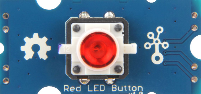
The Grove-LED Button is a versatile module that combines an LED and a push button into a single, compact unit. This module allows users to control the LED's state (on/off) with the press of a button, making it ideal for interactive projects. It is part of the Grove ecosystem, which simplifies prototyping and development by using standardized connectors and plug-and-play functionality.
Explore Projects Built with Grove-LED Button

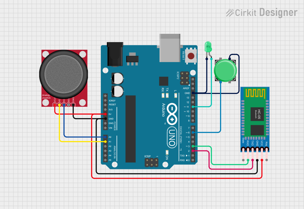

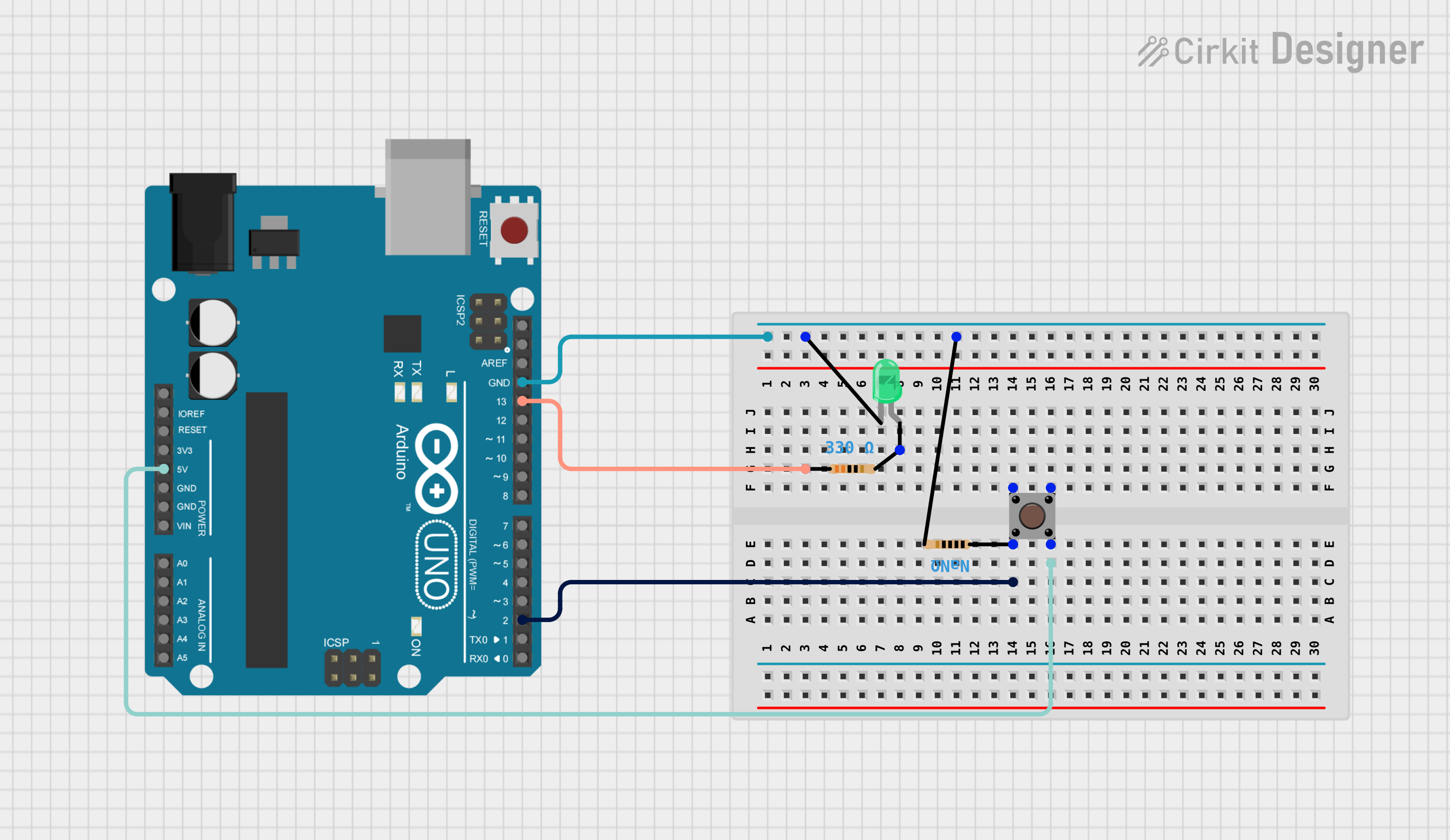
Explore Projects Built with Grove-LED Button
Common Applications and Use Cases
- Interactive projects and prototypes
- User input interfaces
- Visual feedback systems
- Educational projects for learning electronics
- DIY projects requiring simple button and LED integration
Technical Specifications
The Grove-LED Button is designed for ease of use and compatibility with microcontrollers like Arduino, Raspberry Pi, and others. Below are its key technical details:
Key Technical Details
| Parameter | Value |
|---|---|
| Operating Voltage | 3.3V / 5V |
| Operating Current | ≤ 20mA |
| LED Color | Red |
| Button Type | Momentary Push Button |
| Connector Type | Grove 4-pin Interface |
| Dimensions | 20mm x 20mm |
| Weight | 3g |
Pin Configuration and Descriptions
The Grove-LED Button uses a 4-pin Grove connector. The pinout is as follows:
| Pin Number | Pin Name | Description |
|---|---|---|
| 1 | VCC | Power supply (3.3V or 5V) |
| 2 | GND | Ground |
| 3 | SIG_LED | Signal pin to control the LED |
| 4 | SIG_BTN | Signal pin to read the button's state |
Usage Instructions
The Grove-LED Button is straightforward to use in a circuit. Follow the steps below to integrate it into your project:
Connecting the Grove-LED Button
Hardware Setup:
- Connect the Grove-LED Button to a Grove Base Shield or directly to your microcontroller using a Grove cable.
- Ensure the module is connected to a digital I/O port (e.g., D2 or D3 on an Arduino UNO).
Circuit Diagram:
- The SIG_LED pin is connected to a digital output pin on the microcontroller to control the LED.
- The SIG_BTN pin is connected to a digital input pin to read the button's state.
Example Code for Arduino UNO
Below is an example Arduino sketch to demonstrate how to use the Grove-LED Button. The code toggles the LED state each time the button is pressed.
// Define the pin numbers for the LED and button
const int ledPin = 2;  // Connect SIG_LED to digital pin 2
const int buttonPin = 3;  // Connect SIG_BTN to digital pin 3

// Variable to store the button state
int buttonState = 0;
// Variable to track the LED state
bool ledState = false;

void setup() {
  // Initialize the LED pin as an output
  pinMode(ledPin, OUTPUT);
  // Initialize the button pin as an input
  pinMode(buttonPin, INPUT);
  // Start the serial monitor for debugging
  Serial.begin(9600);
}

void loop() {
  // Read the current state of the button
  buttonState = digitalRead(buttonPin);

  // Check if the button is pressed
  if (buttonState == HIGH) {
    // Toggle the LED state
    ledState = !ledState;
    // Update the LED output
    digitalWrite(ledPin, ledState ? HIGH : LOW);
    // Print the LED state to the serial monitor
    Serial.print("LED is now: ");
    Serial.println(ledState ? "ON" : "OFF");

    // Debounce delay to avoid multiple toggles
    delay(200);
  }
}
Important Considerations and Best Practices
- Debouncing: The button may produce multiple signals due to mechanical bouncing. Use a small delay (e.g., 200ms) to debounce the button.
- Voltage Compatibility: Ensure the module is powered with the correct voltage (3.3V or 5V) to avoid damage.
- Signal Pins: Avoid connecting the SIG_LED or SIG_BTN pins directly to VCC or GND without proper current-limiting resistors or microcontroller control.
Troubleshooting and FAQs
Common Issues and Solutions
The LED does not light up:
- Verify that the SIG_LED pin is connected to a digital output pin on the microcontroller.
- Check the power supply voltage (3.3V or 5V) and ensure proper connections.
The button press is not detected:
- Ensure the SIG_BTN pin is connected to a digital input pin on the microcontroller.
- Check for loose or incorrect connections in the Grove cable.
The LED flickers or behaves erratically:
- This may be caused by button debounce issues. Add a small delay (e.g., 200ms) in the code after detecting a button press.
The module does not work at all:
- Confirm that the Grove Base Shield or Grove cable is properly connected.
- Test the module with a different digital I/O port on the microcontroller.
FAQs
Q: Can I use the Grove-LED Button with a Raspberry Pi?
A: Yes, the module can be used with a Raspberry Pi. Use the GPIO pins to control the LED and read the button state. You may need a Grove Pi+ or Grove HAT for easier integration.
Q: Can I change the LED color?
A: The module comes with a fixed red LED. To use a different color, you would need to modify the hardware by replacing the LED.
Q: Is the button latching or momentary?
A: The button is momentary, meaning it only stays pressed while you hold it down.
Q: Can I use this module with 3.3V systems?
A: Yes, the Grove-LED Button is compatible with both 3.3V and 5V systems.
By following this documentation, you can easily integrate the Grove-LED Button into your projects and troubleshoot any issues that arise. Happy prototyping!