How to Use Motor: Examples, Pinouts, and Specs
Introduction
A motor is an electromechanical device that converts electrical energy into mechanical energy. It is a fundamental component in countless applications, ranging from industrial machinery to consumer electronics. Motors are used to drive mechanical systems, perform work, or enable motion in devices such as fans, robots, conveyor belts, and vehicles.
Explore Projects Built with Motor

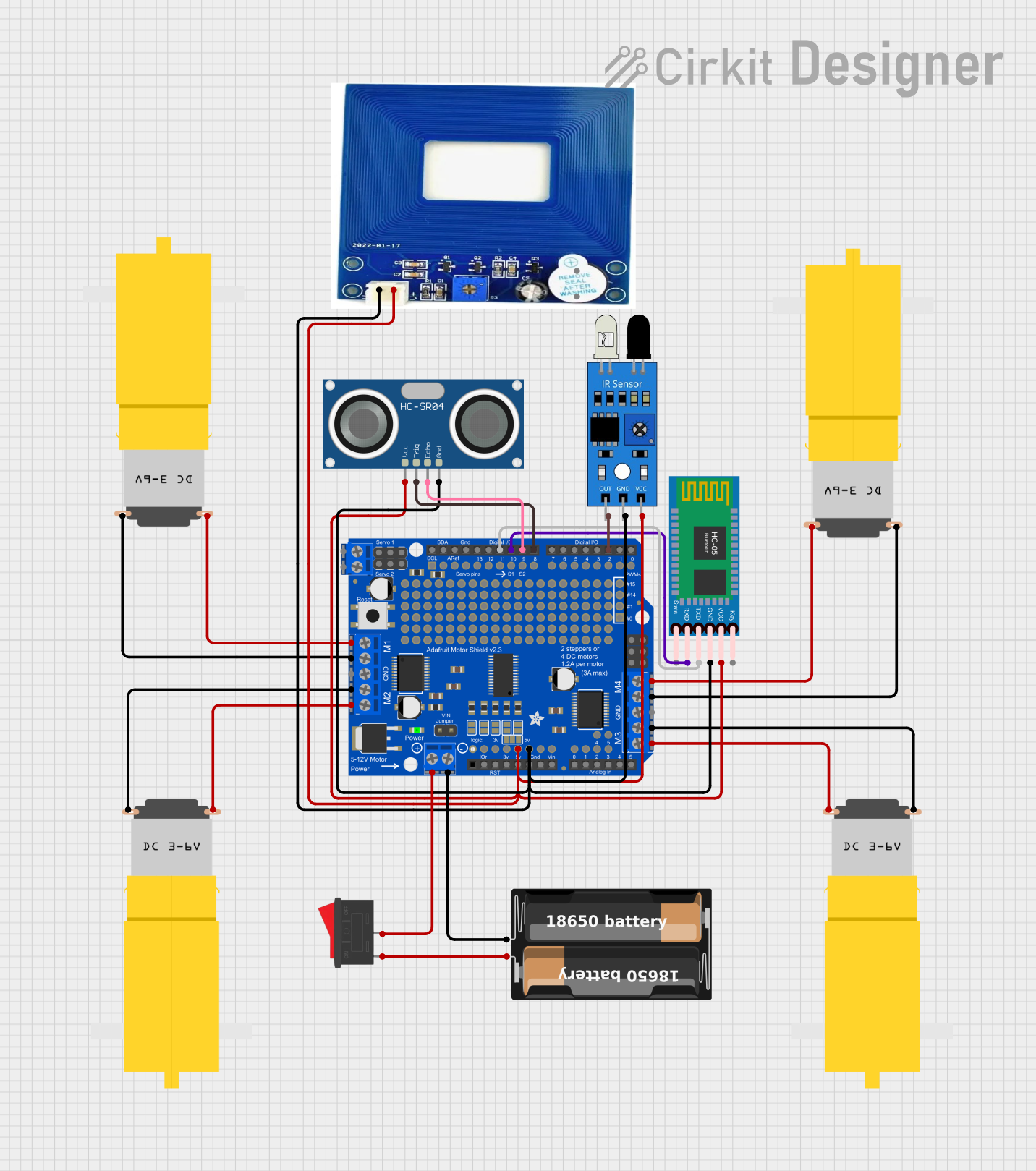
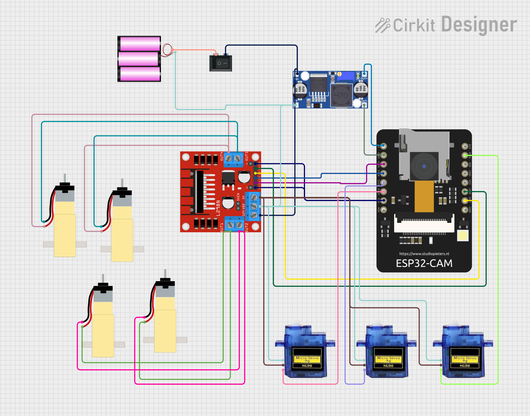
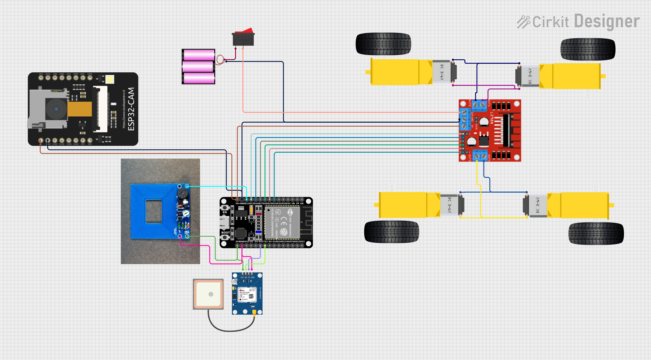
Explore Projects Built with Motor
Common Applications and Use Cases
- Robotics: Driving wheels, arms, or other moving parts.
- Industrial Automation: Operating conveyor belts, pumps, and machine tools.
- Consumer Electronics: Powering fans, hard drives, and household appliances.
- Automotive: Enabling electric vehicle propulsion or auxiliary systems like windshield wipers.
- HVAC Systems: Driving compressors, blowers, and fans.
Technical Specifications
Motors come in various types, such as DC motors, stepper motors, and AC motors. Below are the general technical specifications for a typical DC motor:
General Specifications
- Operating Voltage: 3V to 12V (varies by model)
- Current Rating: 100mA to 2A (depending on load)
- Power Output: Up to 10W (varies by size and type)
- Speed: 1000 to 10,000 RPM (Revolutions Per Minute)
- Torque: 0.1 to 2 Nm (Newton-meters)
- Type: Brushed or Brushless
Pin Configuration and Descriptions
For a basic DC motor, the pin configuration is straightforward:
| Pin Name | Description |
|---|---|
| V+ | Positive terminal for power input. |
| V- | Negative terminal (ground). |
For more complex motors, such as stepper motors, the pin configuration may include multiple control pins:
| Pin Name | Description |
|---|---|
| A+ | Coil A positive terminal. |
| A- | Coil A negative terminal. |
| B+ | Coil B positive terminal. |
| B- | Coil B negative terminal. |
| EN | Enable pin (optional, for motor drivers). |
Usage Instructions
How to Use the Motor in a Circuit
- Power Supply: Ensure the motor is powered within its specified voltage range. Use a regulated power supply or batteries.
- Motor Driver: For most motors, especially DC and stepper motors, use a motor driver (e.g., L298N or L293D) to control the motor safely and efficiently.
- Connections:
- Connect the motor terminals to the motor driver outputs.
- Connect the motor driver inputs to a microcontroller (e.g., Arduino UNO) or control circuit.
- Control Signals: Use Pulse Width Modulation (PWM) to control the motor's speed and direction.
Important Considerations and Best Practices
- Current Limiting: Ensure the motor driver can handle the motor's stall current to prevent damage.
- Heat Dissipation: Motors can generate heat during operation. Provide adequate ventilation or heat sinks if necessary.
- Load Matching: Avoid overloading the motor beyond its rated torque to prevent stalling or damage.
- Reverse Polarity: Ensure correct polarity when connecting the motor to avoid damage.
Example: Controlling a DC Motor with Arduino UNO
Below is an example of controlling a DC motor using an Arduino UNO and an L298N motor driver:
// Arduino code to control a DC motor using L298N motor driver
// Connect IN1 and IN2 of the L298N to Arduino pins 9 and 10 respectively
// Connect ENA of the L298N to Arduino pin 3 (PWM pin)

#define IN1 9  // Motor driver input 1
#define IN2 10 // Motor driver input 2
#define ENA 3  // Motor driver enable pin (PWM)

void setup() {
  pinMode(IN1, OUTPUT); // Set IN1 as output
  pinMode(IN2, OUTPUT); // Set IN2 as output
  pinMode(ENA, OUTPUT); // Set ENA as output
}

void loop() {
  // Rotate motor forward
  digitalWrite(IN1, HIGH); // Set IN1 high
  digitalWrite(IN2, LOW);  // Set IN2 low
  analogWrite(ENA, 128);   // Set speed to 50% (PWM value: 128 out of 255)
  delay(2000);             // Run for 2 seconds

  // Stop motor
  digitalWrite(IN1, LOW);  // Set IN1 low
  digitalWrite(IN2, LOW);  // Set IN2 low
  delay(1000);             // Wait for 1 second

  // Rotate motor backward
  digitalWrite(IN1, LOW);  // Set IN1 low
  digitalWrite(IN2, HIGH); // Set IN2 high
  analogWrite(ENA, 128);   // Set speed to 50% (PWM value: 128 out of 255)
  delay(2000);             // Run for 2 seconds

  // Stop motor
  digitalWrite(IN1, LOW);  // Set IN1 low
  digitalWrite(IN2, LOW);  // Set IN2 low
  delay(1000);             // Wait for 1 second
}
Troubleshooting and FAQs
Common Issues
- Motor Not Spinning:
- Check the power supply and ensure the voltage matches the motor's requirements.
- Verify the motor driver connections and ensure the control signals are correct.
- Overheating:
- Ensure the motor is not overloaded or running at excessive speeds.
- Provide proper ventilation or heat dissipation.
- Erratic Movement:
- Check for loose connections or faulty wiring.
- Verify the control signals and ensure they are stable.
Solutions and Tips for Troubleshooting
- Use a multimeter to check voltage and current at the motor terminals.
- Test the motor with a direct power supply to confirm it is functional.
- If using a motor driver, ensure it is compatible with the motor's voltage and current ratings.
- For stepper motors, ensure the step sequence and timing are correct.
By following this documentation, you can effectively integrate and troubleshoot motors in your projects.