How to Use JST SH1 x8 Male: Examples, Pinouts, and Specs
Introduction
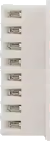
The JST SH1 x8 Male is a compact, 1.0mm pitch connector designed for reliable and space-efficient wire-to-board or wire-to-wire connections in electronic circuits. With 8 pins, it provides multiple connection points, making it ideal for applications requiring compact and precise wiring. Its small form factor and robust design make it a popular choice in consumer electronics, robotics, drones, and other devices where space is limited.
Explore Projects Built with JST SH1 x8 Male


Explore Projects Built with JST SH1 x8 Male
Common Applications
- Connecting sensors, actuators, or modules in compact devices
- Wiring for drones, RC vehicles, and robotics
- Consumer electronics such as cameras, wearables, and handheld devices
- Prototyping and small-scale production circuits
Technical Specifications
Below are the key technical details of the JST SH1 x8 Male connector:
| Parameter | Specification |
|---|---|
| Pitch | 1.0mm |
| Number of Pins | 8 |
| Current Rating | 0.5A per pin |
| Voltage Rating | 50V DC |
| Contact Resistance | ≤ 20mΩ |
| Insulation Resistance | ≥ 500MΩ |
| Operating Temperature | -25°C to +85°C |
| Connector Type | Male (plug) |
| Mounting Style | Wire-to-board or wire-to-wire |
Pin Configuration and Descriptions
The JST SH1 x8 Male connector has 8 pins arranged in a single row with a 1.0mm pitch. Below is the pin configuration:
| Pin Number | Description |
|---|---|
| 1 | Signal/Power Line 1 |
| 2 | Signal/Power Line 2 |
| 3 | Signal/Power Line 3 |
| 4 | Signal/Power Line 4 |
| 5 | Signal/Power Line 5 |
| 6 | Signal/Power Line 6 |
| 7 | Signal/Power Line 7 |
| 8 | Signal/Power Line 8 |
Note: Pin assignments depend on the specific application and circuit design. Always refer to the circuit schematic for proper pin usage.
Usage Instructions
How to Use the JST SH1 x8 Male Connector
Prepare the Wires:
- Strip the insulation from the wires to expose approximately 1-2mm of the conductor.
- Ensure the wires are clean and free of damage.
Crimp the Contacts:
- Use a compatible crimping tool to attach the crimp terminals to the wires.
- Ensure the crimp is secure to avoid loose connections.
Insert the Contacts:
- Insert the crimped wires into the connector housing until they click into place.
- Verify that all contacts are properly seated and aligned.
Connect to the Mating Connector:
- Align the JST SH1 x8 Male connector with its corresponding female connector.
- Gently push the connectors together until they lock securely.
Important Considerations
- Wire Gauge: Use wires with an appropriate gauge (typically 28-32 AWG) to ensure compatibility with the connector.
- Mating Cycles: The connector is rated for a limited number of mating cycles (approximately 50). Avoid excessive disconnections to maintain reliability.
- Polarity: Ensure correct orientation when connecting to avoid short circuits or damage to the circuit.
- Soldering: If soldering is required, use a low-temperature soldering iron to avoid damaging the connector.
Example: Connecting to an Arduino UNO
The JST SH1 x8 Male connector can be used to connect sensors or modules to an Arduino UNO. Below is an example of connecting a sensor with an 8-pin JST SH1 connector to the Arduino:
// Example: Reading data from a sensor connected via JST SH1 x8 Male connector
// Pin 1: VCC (3.3V or 5V)
// Pin 2: GND
// Pin 3: Data Line (e.g., SDA for I2C)
// Pin 4: Clock Line (e.g., SCL for I2C)

// Define the I2C pins for Arduino UNO
#include <Wire.h> // Include the Wire library for I2C communication

void setup() {
  Wire.begin(); // Initialize I2C communication
  Serial.begin(9600); // Start serial communication for debugging
  Serial.println("Initializing sensor...");
}

void loop() {
  // Example: Request data from the sensor
  Wire.beginTransmission(0x40); // Replace 0x40 with the sensor's I2C address
  Wire.write(0x00); // Replace 0x00 with the register address to read
  Wire.endTransmission();

  Wire.requestFrom(0x40, 2); // Request 2 bytes of data from the sensor
  if (Wire.available() == 2) {
    int data = Wire.read() << 8 | Wire.read(); // Combine the two bytes
    Serial.print("Sensor Data: ");
    Serial.println(data);
  }

  delay(1000); // Wait 1 second before the next reading
}
Note: The pin assignments (e.g., VCC, GND, SDA, SCL) depend on the specific sensor or module being used. Refer to the sensor's datasheet for details.
Troubleshooting and FAQs
Common Issues
Loose Connections:
- Cause: Improper crimping or insertion of wires.
- Solution: Re-crimp the wires and ensure they are fully inserted into the connector housing.
Incorrect Pin Assignment:
- Cause: Misaligned or incorrect wiring.
- Solution: Double-check the circuit schematic and verify the pin assignments.
Intermittent Signal Loss:
- Cause: Damaged or worn-out connector contacts.
- Solution: Inspect the connector for damage and replace if necessary.
Overheating:
- Cause: Exceeding the current or voltage rating.
- Solution: Ensure the current and voltage do not exceed the specified limits.
FAQs
Q1: Can the JST SH1 x8 Male connector handle high currents?
A1: No, the connector is rated for a maximum current of 0.5A per pin. For higher currents, consider using a connector with a larger pitch and higher current rating.
Q2: Is the JST SH1 x8 Male connector waterproof?
A2: No, this connector is not waterproof. For outdoor or moisture-prone applications, use a waterproof connector.
Q3: Can I solder wires directly to the JST SH1 x8 Male connector?
A3: While possible, it is not recommended as it may damage the connector. Use crimp terminals for a secure and reliable connection.
Q4: How do I remove a wire from the connector housing?
A4: Use a small pin or extraction tool to release the locking tab on the contact, then gently pull the wire out.
By following this documentation, you can effectively use the JST SH1 x8 Male connector in your electronic projects.