Cirkit Designer Logo
Cirkit Designer
Your all-in-one circuit design IDE
Home / 
Component Documentation

How to Use Servo: Examples, Pinouts, and Specs

Image of Servo
Cirkit Designer LogoDesign with Servo in Cirkit Designer

Introduction

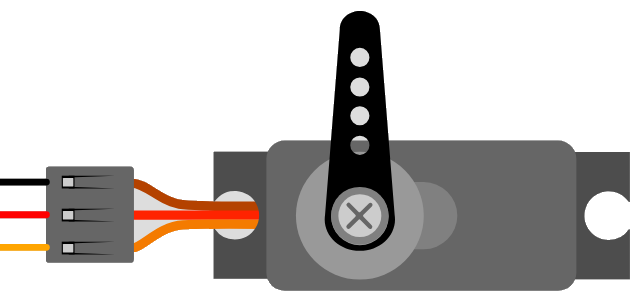
A servo motor is a rotary actuator or linear actuator that allows for precise control of angular or linear position, velocity, and acceleration. It consists of a suitable motor coupled to a sensor for position feedback. Servo motors are widely used in robotics, radio-controlled cars, airplanes, and boats, as well as in industrial applications, such as controlling the motion of robotic arms. The control signal is a digital PWM (Pulse Width Modulation) signal, which determines the position of the shaft of the servo motor.

Explore Projects Built with Servo

Use Cirkit Designer to design, explore, and prototype these projects online. Some projects support real-time simulation. Click "Open Project" to start designing instantly!
Arduino Mega 2560 Controlled Multi-Servo Random Positioning System
Image of robotic: A project utilizing Servo in a practical application
This circuit consists of an Arduino Mega 2560 microcontroller connected to twelve servo motors, each individually controlled by a distinct PWM pin on the Arduino. The servos are powered by a single Polymer Lithium Ion Battery, with all servos sharing a common power (VCC) and ground (GND) connection. The embedded code on the Arduino is designed to randomly position each servo within a 0 to 180-degree range, with a random delay between movements, demonstrating a multi-servo control system possibly for applications like robotics or animatronics.
Cirkit Designer LogoOpen Project in Cirkit Designer
Arduino UNO Servo Motor Controller
Image of Test project: A project utilizing Servo in a practical application
This circuit consists of an Arduino UNO microcontroller connected to a servo motor. The Arduino provides power (5V and GND) to the servo and controls its position through a pulse signal on pin D9. The embedded code on the Arduino is programmed to smoothly move the servo between 0 and 180 degrees, creating a sweeping motion.
Cirkit Designer LogoOpen Project in Cirkit Designer
Arduino UNO Controlled Servo Motor
Image of lblblblb: A project utilizing Servo in a practical application
This circuit consists of an Arduino UNO microcontroller connected to a servo motor. The Arduino provides power (5V) and ground connections to the servo, as well as a control signal through one of its digital pins (D6). The embedded code on the Arduino is set up to control the servo's position, sending it to a fixed angle upon each loop iteration.
Cirkit Designer LogoOpen Project in Cirkit Designer
Arduino-Controlled Multi-Servo System
Image of Mind controlled robotic arm: A project utilizing Servo in a practical application
This circuit consists of an Arduino UNO microcontroller connected to five servo motors. The servos are powered by the Arduino's 5V output and share a common ground. Each servo's PWM control pin is individually connected to a digital pin on the Arduino (D8, D9, D10, D11, D12), allowing for independent control of each servo's position. The Arduino is also connected to a laptop via USB for programming and power.
Cirkit Designer LogoOpen Project in Cirkit Designer

Explore Projects Built with Servo

Use Cirkit Designer to design, explore, and prototype these projects online. Some projects support real-time simulation. Click "Open Project" to start designing instantly!
Image of robotic: A project utilizing Servo in a practical application
Arduino Mega 2560 Controlled Multi-Servo Random Positioning System
This circuit consists of an Arduino Mega 2560 microcontroller connected to twelve servo motors, each individually controlled by a distinct PWM pin on the Arduino. The servos are powered by a single Polymer Lithium Ion Battery, with all servos sharing a common power (VCC) and ground (GND) connection. The embedded code on the Arduino is designed to randomly position each servo within a 0 to 180-degree range, with a random delay between movements, demonstrating a multi-servo control system possibly for applications like robotics or animatronics.
Cirkit Designer LogoOpen Project in Cirkit Designer
Image of Test project: A project utilizing Servo in a practical application
Arduino UNO Servo Motor Controller
This circuit consists of an Arduino UNO microcontroller connected to a servo motor. The Arduino provides power (5V and GND) to the servo and controls its position through a pulse signal on pin D9. The embedded code on the Arduino is programmed to smoothly move the servo between 0 and 180 degrees, creating a sweeping motion.
Cirkit Designer LogoOpen Project in Cirkit Designer
Image of lblblblb: A project utilizing Servo in a practical application
Arduino UNO Controlled Servo Motor
This circuit consists of an Arduino UNO microcontroller connected to a servo motor. The Arduino provides power (5V) and ground connections to the servo, as well as a control signal through one of its digital pins (D6). The embedded code on the Arduino is set up to control the servo's position, sending it to a fixed angle upon each loop iteration.
Cirkit Designer LogoOpen Project in Cirkit Designer
Image of Mind controlled robotic arm: A project utilizing Servo in a practical application
Arduino-Controlled Multi-Servo System
This circuit consists of an Arduino UNO microcontroller connected to five servo motors. The servos are powered by the Arduino's 5V output and share a common ground. Each servo's PWM control pin is individually connected to a digital pin on the Arduino (D8, D9, D10, D11, D12), allowing for independent control of each servo's position. The Arduino is also connected to a laptop via USB for programming and power.
Cirkit Designer LogoOpen Project in Cirkit Designer

Technical Specifications

Key Technical Details

  • Voltage Range: Typically 4.8V to 6V for standard servos.
  • Current Consumption: Varies with load, typically up to 1A at peak for standard servos.
  • Torque: Depends on the model, can range from 1.5 kg-cm to 20 kg-cm or more.
  • Speed: Varies by model, with typical speeds from 0.10 to 0.20 seconds per 60-degree movement.
  • Rotation Angle: Usually 0 to 180 degrees, some servos offer more extended ranges.
  • Control Signal: PWM, typically a 1-2 ms pulse every 20 ms corresponds to 0-180 degrees.

Pin Configuration and Descriptions

Pin Name Description
VCC Power supply (4.8V to 6V)
GND Ground connection
SIGNAL PWM control signal input

Usage Instructions

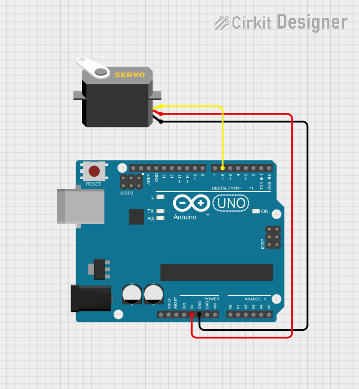
Connecting to a Circuit

  1. Connect the VCC pin to a suitable power supply (4.8V to 6V).
  2. Connect the GND pin to the ground of the power supply.
  3. Connect the SIGNAL pin to a PWM-capable pin on your microcontroller, such as an Arduino UNO.

Important Considerations and Best Practices

  • Ensure that the power supply can handle the current requirements of the servo.
  • Avoid stalling the servo as it can lead to high current draw and potential damage.
  • Use a separate power supply if the servo's current draw is too high for the microcontroller's voltage regulator.
  • Keep the control signal within the specified pulse width range to prevent damage to the servo.

Example Code for Arduino UNO

#include <Servo.h>

Servo myservo;  // create servo object to control a servo

void setup() {
  myservo.attach(9);  // attaches the servo on pin 9 to the servo object
}

void loop() {
  myservo.write(90);  // sets the servo position to 90 degrees
  delay(1000);        // waits for the servo to reach the position
  myservo.write(0);   // sets the servo position to 0 degrees
  delay(1000);        // waits for the servo to reach the position
}

Troubleshooting and FAQs

Common Issues

  • Servo not moving: Check the power supply and connections. Ensure the control signal is being sent correctly.
  • Erratic movement: This can be caused by an inadequate power supply or noise in the control signal. Ensure a stable power source and signal.
  • Overheating: Continuous operation under load or stalling can cause overheating. Allow the servo to cool down.

Solutions and Tips

  • Use a multimeter to check for proper voltage at the servo's power pins.
  • If using long wires, consider using a twisted pair for the signal and ground to reduce noise.
  • For high-power servos, use a dedicated power supply and ensure all connections are secure.

FAQs

Q: Can I control a servo with a 3.3V microcontroller like an Arduino Due? A: Yes, but ensure that the servo can handle the 3.3V control signal. Some servos require a 5V signal.

Q: How can I control a servo with a higher voltage or current rating? A: Use an external power supply that matches the servo's requirements, and connect the ground of the power supply to the ground of the microcontroller.

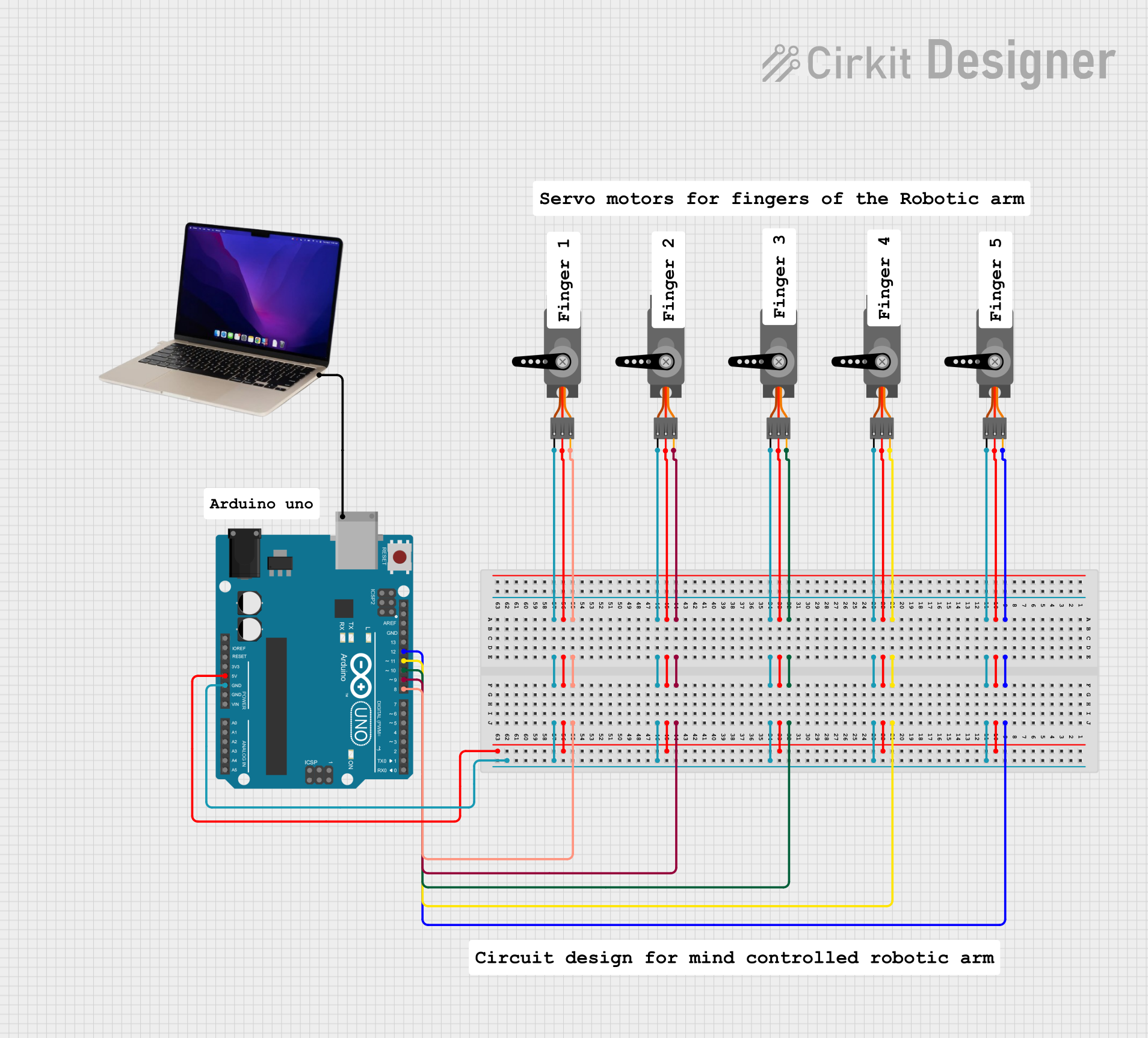
Q: Can I control more than one servo with an Arduino? A: Yes, you can control multiple servos by using multiple PWM-capable pins and creating a Servo object for each one in your code.