Cirkit Designer Logo
Cirkit Designer
Your all-in-one circuit design IDE
Home / 
Component Documentation

How to Use G5: Examples, Pinouts, and Specs

Image of G5
Cirkit Designer LogoDesign with G5 in Cirkit Designer

Introduction

The Garmin G5 is a versatile relay designed for use in electronic circuits to control the flow of current. It operates by using an electromagnetic coil to open or close a set of contacts, enabling the automation of electrical devices. Relays like the G5 are essential in applications where low-power control signals are used to manage high-power circuits.

Explore Projects Built with G5

Use Cirkit Designer to design, explore, and prototype these projects online. Some projects support real-time simulation. Click "Open Project" to start designing instantly!
Arduino UNO and A9G GSM/GPRS GPS-Based Air Quality Monitoring System
Image of A9G Smoke Sensor: A project utilizing G5 in a practical application
This circuit features an Arduino UNO microcontroller interfaced with an A9G GSM/GPRS+GPS module and an MQ2 gas sensor. The Arduino communicates with the A9G module via digital pins D11 and D10 for data transmission, and it reads analog gas concentration levels from the MQ2 sensor through analog pin A5. Both the A9G module and the MQ2 sensor are powered by the Arduino's 5V output, and all components share a common ground.
Cirkit Designer LogoOpen Project in Cirkit Designer
Solar-Powered GSM/GPRS+GPS Tracker with Seeeduino XIAO
Image of SOS System : A project utilizing G5 in a practical application
This circuit features an Ai Thinker A9G development board for GSM/GPRS and GPS/BDS connectivity, interfaced with a Seeeduino XIAO microcontroller for control and data processing. A solar cell, coupled with a TP4056 charging module, charges a 3.3V battery, which powers the system through a 3.3V regulator ensuring stable operation. The circuit likely serves for remote data communication and location tracking, with the capability to be powered by renewable energy and interfaced with additional sensors or input devices via the Seeeduino XIAO.
Cirkit Designer LogoOpen Project in Cirkit Designer
Raspberry Pi 5-Based Project with Custom Comments
Image of Raspberry Pi 5: A project utilizing G5 in a practical application
The circuit consists of a Raspberry Pi 5 with no additional electrical connections or code, suggesting it is either a placeholder for future development or a standalone component without any external interfacing in this configuration.
Cirkit Designer LogoOpen Project in Cirkit Designer
Arduino Mega 2560 Based Security System with Fingerprint Authentication and SMS Alerts
Image of Door security system: A project utilizing G5 in a practical application
This circuit features an Arduino Mega 2560 microcontroller interfaced with a SIM800L GSM module, two fingerprint scanners, an I2C LCD display, an IR sensor, and a piezo buzzer. Power management is handled by a PowerBoost 1000 Basic Pad USB, a TP4056 charging module, and a Li-ion 18650 battery, with an option to use a Mini AC-DC 110V-230V to 5V 700mA module for direct power supply. The primary functionality appears to be a security system with GSM communication capabilities, biometric access control, and visual/audible feedback.
Cirkit Designer LogoOpen Project in Cirkit Designer

Explore Projects Built with G5

Use Cirkit Designer to design, explore, and prototype these projects online. Some projects support real-time simulation. Click "Open Project" to start designing instantly!
Image of A9G Smoke Sensor: A project utilizing G5 in a practical application
Arduino UNO and A9G GSM/GPRS GPS-Based Air Quality Monitoring System
This circuit features an Arduino UNO microcontroller interfaced with an A9G GSM/GPRS+GPS module and an MQ2 gas sensor. The Arduino communicates with the A9G module via digital pins D11 and D10 for data transmission, and it reads analog gas concentration levels from the MQ2 sensor through analog pin A5. Both the A9G module and the MQ2 sensor are powered by the Arduino's 5V output, and all components share a common ground.
Cirkit Designer LogoOpen Project in Cirkit Designer
Image of SOS System : A project utilizing G5 in a practical application
Solar-Powered GSM/GPRS+GPS Tracker with Seeeduino XIAO
This circuit features an Ai Thinker A9G development board for GSM/GPRS and GPS/BDS connectivity, interfaced with a Seeeduino XIAO microcontroller for control and data processing. A solar cell, coupled with a TP4056 charging module, charges a 3.3V battery, which powers the system through a 3.3V regulator ensuring stable operation. The circuit likely serves for remote data communication and location tracking, with the capability to be powered by renewable energy and interfaced with additional sensors or input devices via the Seeeduino XIAO.
Cirkit Designer LogoOpen Project in Cirkit Designer
Image of Raspberry Pi 5: A project utilizing G5 in a practical application
Raspberry Pi 5-Based Project with Custom Comments
The circuit consists of a Raspberry Pi 5 with no additional electrical connections or code, suggesting it is either a placeholder for future development or a standalone component without any external interfacing in this configuration.
Cirkit Designer LogoOpen Project in Cirkit Designer
Image of Door security system: A project utilizing G5 in a practical application
Arduino Mega 2560 Based Security System with Fingerprint Authentication and SMS Alerts
This circuit features an Arduino Mega 2560 microcontroller interfaced with a SIM800L GSM module, two fingerprint scanners, an I2C LCD display, an IR sensor, and a piezo buzzer. Power management is handled by a PowerBoost 1000 Basic Pad USB, a TP4056 charging module, and a Li-ion 18650 battery, with an option to use a Mini AC-DC 110V-230V to 5V 700mA module for direct power supply. The primary functionality appears to be a security system with GSM communication capabilities, biometric access control, and visual/audible feedback.
Cirkit Designer LogoOpen Project in Cirkit Designer

Common Applications and Use Cases

  • Home automation systems
  • Industrial control panels
  • Automotive electronics
  • Power supply switching
  • Motor control circuits
  • Signal isolation between high- and low-voltage systems

Technical Specifications

Key Technical Details

  • Manufacturer: Garmin
  • Part ID: G5
  • Type: Electromechanical relay
  • Coil Voltage: 5V DC (typical)
  • Contact Configuration: SPDT (Single Pole Double Throw)
  • Contact Rating: 10A at 250V AC or 10A at 30V DC
  • Coil Resistance: 70Ω ±10%
  • Switching Time: 10ms (operate) / 5ms (release)
  • Dielectric Strength: 1500V AC (coil to contacts)
  • Insulation Resistance: ≥100MΩ at 500V DC
  • Operating Temperature Range: -40°C to +85°C
  • Dimensions: 28mm x 12mm x 15mm

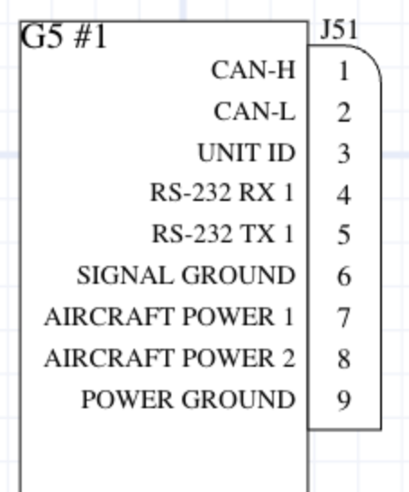
Pin Configuration and Descriptions

The G5 relay typically has 5 pins, as described in the table below:

Pin Number Name Description
1 Coil (+) Positive terminal of the relay coil. Connect to the control voltage source.
2 Coil (-) Negative terminal of the relay coil. Connect to ground.
3 Common (COM) Common terminal for the relay contacts.
4 Normally Closed (NC) Contact that is connected to COM when the relay is not energized.
5 Normally Open (NO) Contact that is connected to COM when the relay is energized.

Usage Instructions

How to Use the G5 in a Circuit

  1. Power the Coil: Connect the coil pins (1 and 2) to a 5V DC power source. Use a current-limiting resistor if necessary to prevent overloading the coil.
  2. Control the Load: Connect the load to the COM (pin 3) and either the NC (pin 4) or NO (pin 5) terminal, depending on whether you want the load to be powered when the relay is de-energized or energized.
  3. Switching Logic: Apply a control signal to the coil to energize the relay. This will switch the connection between the COM and NO terminals, allowing current to flow through the load.

Important Considerations and Best Practices

  • Diode Protection: Place a flyback diode across the coil terminals to protect the circuit from voltage spikes caused by the collapsing magnetic field when the relay is de-energized.
  • Contact Ratings: Ensure the load does not exceed the relay's contact rating (10A at 250V AC or 30V DC).
  • Isolation: Use optocouplers or transistors to isolate the control circuit from the relay if necessary.
  • Mounting: Secure the relay in a socket or PCB to prevent mechanical stress on the pins.

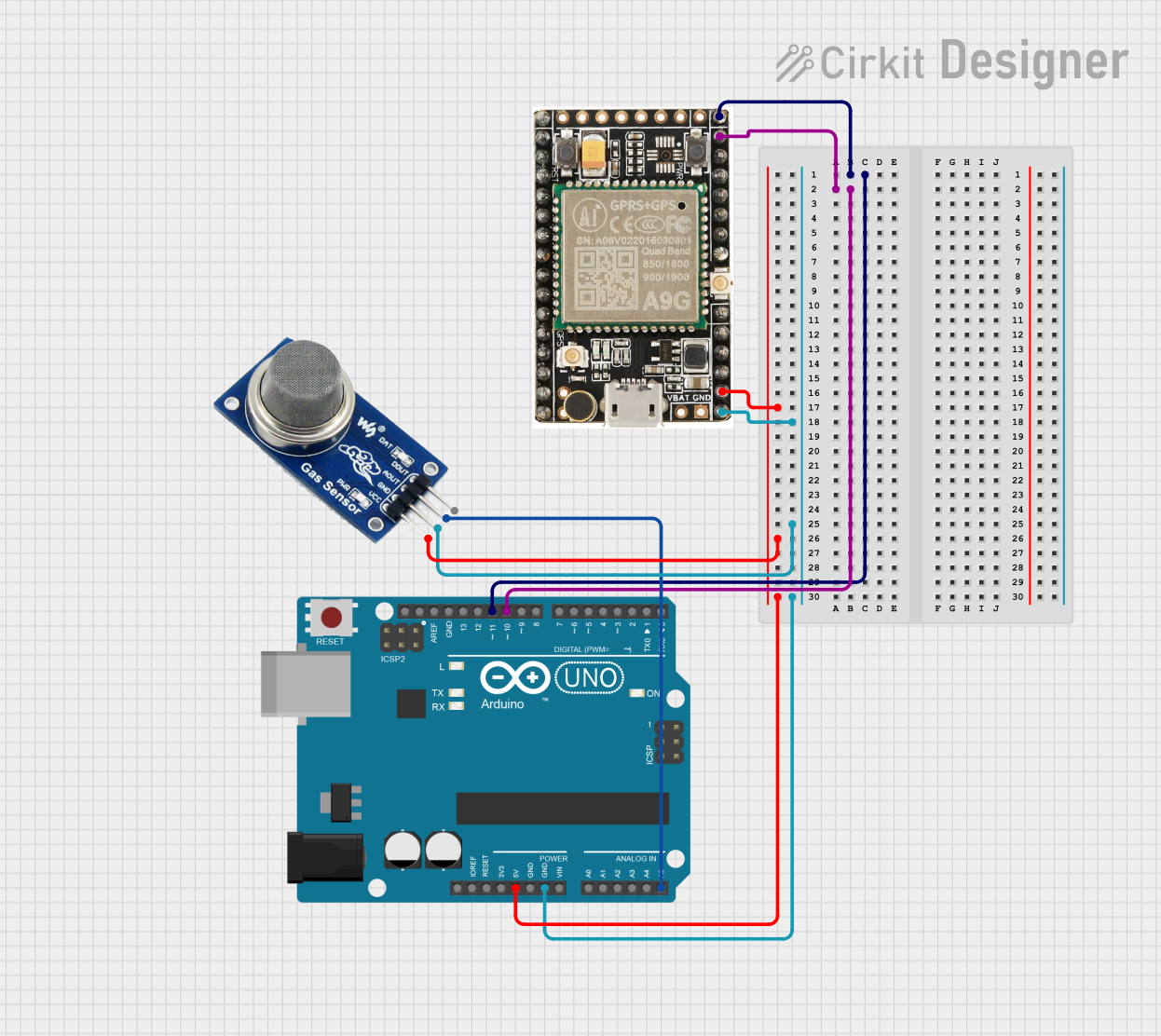
Example: Connecting the G5 to an Arduino UNO

Below is an example of how to control the G5 relay using an Arduino UNO:

// Define the pin connected to the relay's coil
const int relayPin = 7;

void setup() {
  // Set the relay pin as an output
  pinMode(relayPin, OUTPUT);
}

void loop() {
  // Turn the relay ON
  digitalWrite(relayPin, HIGH);
  delay(1000); // Keep the relay ON for 1 second

  // Turn the relay OFF
  digitalWrite(relayPin, LOW);
  delay(1000); // Keep the relay OFF for 1 second
}

Note: Use a transistor (e.g., 2N2222) to drive the relay if the Arduino pin cannot supply enough current. Place a flyback diode (e.g., 1N4007) across the relay coil to protect the transistor and Arduino.

Troubleshooting and FAQs

Common Issues and Solutions

  1. Relay Not Switching:

    • Cause: Insufficient voltage or current to the coil.
    • Solution: Verify the power supply voltage and ensure it matches the relay's coil voltage (5V DC). Check for loose connections.
  2. Contacts Not Conducting:

    • Cause: Load exceeds the relay's contact rating.
    • Solution: Ensure the load current and voltage are within the specified limits (10A at 250V AC or 30V DC).
  3. Coil Overheating:

    • Cause: Continuous overvoltage applied to the coil.
    • Solution: Use a regulated power supply and verify the coil voltage does not exceed 5V DC.
  4. Noise or Chattering:

    • Cause: Unstable control signal or insufficient power supply.
    • Solution: Use a capacitor to stabilize the power supply and ensure the control signal is steady.

FAQs

  • Q: Can the G5 relay handle DC loads?
    A: Yes, the G5 relay can handle DC loads up to 10A at 30V DC.

  • Q: Is the G5 relay suitable for high-frequency switching?
    A: No, the G5 is not designed for high-frequency switching. It is best suited for low-frequency applications.

  • Q: Can I use the G5 relay with a 3.3V microcontroller?
    A: Yes, but you will need a transistor to drive the relay, as the coil requires 5V DC to operate.

  • Q: How do I protect the relay from voltage spikes?
    A: Use a flyback diode (e.g., 1N4007) across the coil terminals to suppress voltage spikes when the relay is de-energized.