
How to Use MAX17048: Examples, Pinouts, and Specs
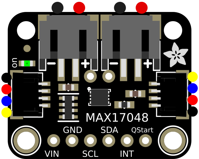
 Design with MAX17048 in Cirkit Designer
Introduction
The MAX17048 is a battery fuel gauge integrated circuit (IC) designed to provide accurate state-of-charge (SOC) information for single-cell lithium-ion (Li-ion) batteries. Unlike traditional fuel gauges, the MAX17048 employs a sophisticated model-based algorithm to estimate the remaining battery capacity without requiring a current-sense resistor. This makes it highly efficient and easy to integrate into compact designs.
Explore Projects Built with MAX17048
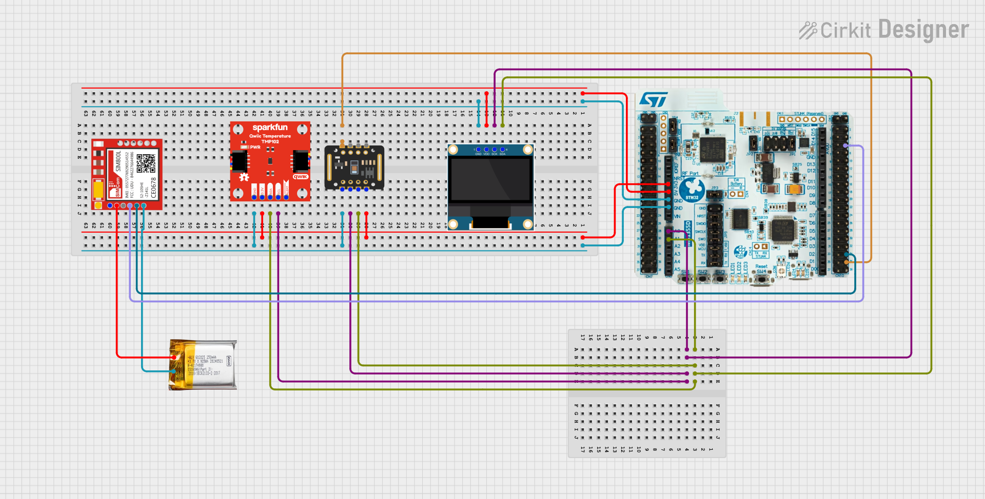
 Open Project in Cirkit Designer
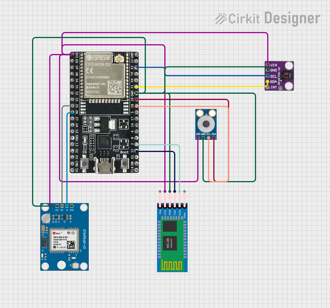
 Open Project in Cirkit Designer
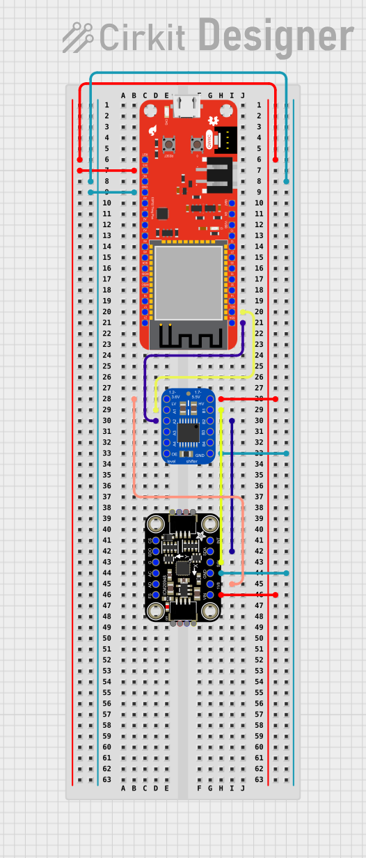
 Open Project in Cirkit Designer
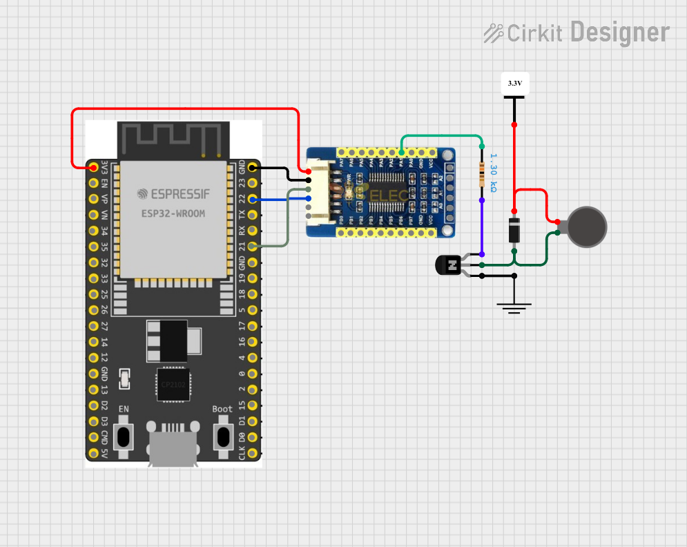
 Open Project in Cirkit Designer
Explore Projects Built with MAX17048

 Open Project in Cirkit Designer
 Open Project in Cirkit Designer
 Open Project in Cirkit Designer
 Open Project in Cirkit Designer
Common Applications
- Smartphones and tablets
- Wearable devices
- Portable medical equipment
- Wireless sensors
- Internet of Things (IoT) devices
The MAX17048 communicates via an I2C interface, making it compatible with a wide range of microcontrollers and systems.
Technical Specifications
Key Technical Details
| Parameter | Value |
|---|---|
| Operating Voltage Range | 2.5V to 4.5V |
| Battery Type Supported | Single-cell lithium-ion |
| Communication Interface | I2C (7-bit address: 0x36 default) |
| Supply Current | 1.2µA (typical) |
| SOC Accuracy | ±1% |
| Operating Temperature Range | -40°C to +85°C |
| Package Type | 6-pin µDFN (1.5mm x 1.5mm) |
Pin Configuration and Descriptions
| Pin Number | Pin Name | Description |
|---|---|---|
| 1 | VDD | Power supply input (2.5V to 4.5V). |
| 2 | SDA | I2C data line. Connect to the microcontroller. |
| 3 | SCL | I2C clock line. Connect to the microcontroller. |
| 4 | GND | Ground. Connect to the system ground. |
| 5 | THRM | Optional thermistor input for temperature monitoring. |
| 6 | BAT | Battery connection. Connect to the positive terminal of the battery. |
Usage Instructions
How to Use the MAX17048 in a Circuit
- Power Supply: Connect the VDD pin to a regulated power supply (2.5V to 4.5V). Ensure the GND pin is connected to the system ground.
- Battery Connection: Connect the BAT pin to the positive terminal of the single-cell lithium-ion battery.
- I2C Communication: Connect the SDA and SCL pins to the corresponding I2C lines of the microcontroller. Use pull-up resistors (typically 4.7kΩ) on both lines.
- Optional Thermistor: If temperature monitoring is required, connect a 10kΩ NTC thermistor to the THRM pin. Otherwise, leave it unconnected.
Important Considerations
- Ensure the battery voltage is within the operating range of the MAX17048 (2.5V to 4.5V).
- Use proper decoupling capacitors (e.g., 0.1µF) near the VDD pin to reduce noise.
- The I2C address of the MAX17048 is 0x36 by default. Ensure no other devices on the I2C bus share this address.
Example Code for Arduino UNO
Below is an example of how to interface the MAX17048 with an Arduino UNO to read the state-of-charge (SOC):
#include <Wire.h> // Include the Wire library for I2C communication

#define MAX17048_ADDRESS 0x36 // I2C address of the MAX17048

void setup() {
  Wire.begin(); // Initialize I2C communication
  Serial.begin(9600); // Initialize serial communication for debugging
}

void loop() {
  uint16_t soc = readSOC(); // Read the state-of-charge
  float percentage = soc / 256.0; // Convert to percentage (0-100%)

  Serial.print("Battery SOC: ");
  Serial.print(percentage);
  Serial.println("%");

  delay(1000); // Wait for 1 second before the next reading
}

uint16_t readSOC() {
  Wire.beginTransmission(MAX17048_ADDRESS); // Start communication with MAX17048
  Wire.write(0x04); // Send the register address for SOC
  Wire.endTransmission(false); // End transmission without releasing the bus

  Wire.requestFrom(MAX17048_ADDRESS, 2); // Request 2 bytes of data
  uint8_t msb = Wire.read(); // Read the most significant byte
  uint8_t lsb = Wire.read(); // Read the least significant byte

  return (msb << 8) | lsb; // Combine the two bytes into a 16-bit value
}
Code Explanation:
- The
readSOC()function reads the SOC register (address 0x04) from the MAX17048. - The SOC value is a 16-bit number, where the upper byte represents the integer part and the lower byte represents the fractional part (scaled by 1/256).
Troubleshooting and FAQs
Common Issues and Solutions
No I2C Communication:
- Cause: Incorrect wiring or missing pull-up resistors on SDA and SCL lines.
- Solution: Verify the connections and ensure 4.7kΩ pull-up resistors are present.
Incorrect SOC Readings:
- Cause: Battery voltage is outside the operating range or the battery is not properly connected.
- Solution: Check the battery voltage and connections. Ensure the battery is within the 2.5V to 4.5V range.
Device Not Detected on I2C Bus:
- Cause: Address conflict or incorrect I2C address.
- Solution: Ensure no other devices on the I2C bus use the 0x36 address. Double-check the wiring.
Temperature Monitoring Not Working:
- Cause: Thermistor not connected or incorrect thermistor value.
- Solution: Use a 10kΩ NTC thermistor and verify the connection to the THRM pin.
FAQs
Q: Can the MAX17048 be used with batteries other than lithium-ion?
A: No, the MAX17048 is specifically designed for single-cell lithium-ion batteries.Q: What is the typical accuracy of the SOC readings?
A: The MAX17048 provides SOC readings with an accuracy of ±1%.Q: Is it necessary to use the THRM pin?
A: No, the THRM pin is optional. If temperature monitoring is not required, it can be left unconnected.Q: Can the MAX17048 operate at voltages below 2.5V?
A: No, the operating voltage range is 2.5V to 4.5V. Operating below this range may result in incorrect readings or malfunction.
This documentation provides a comprehensive guide to understanding, using, and troubleshooting the MAX17048 battery fuel gauge IC.