How to Use splicing connector 6: Examples, Pinouts, and Specs
Introduction
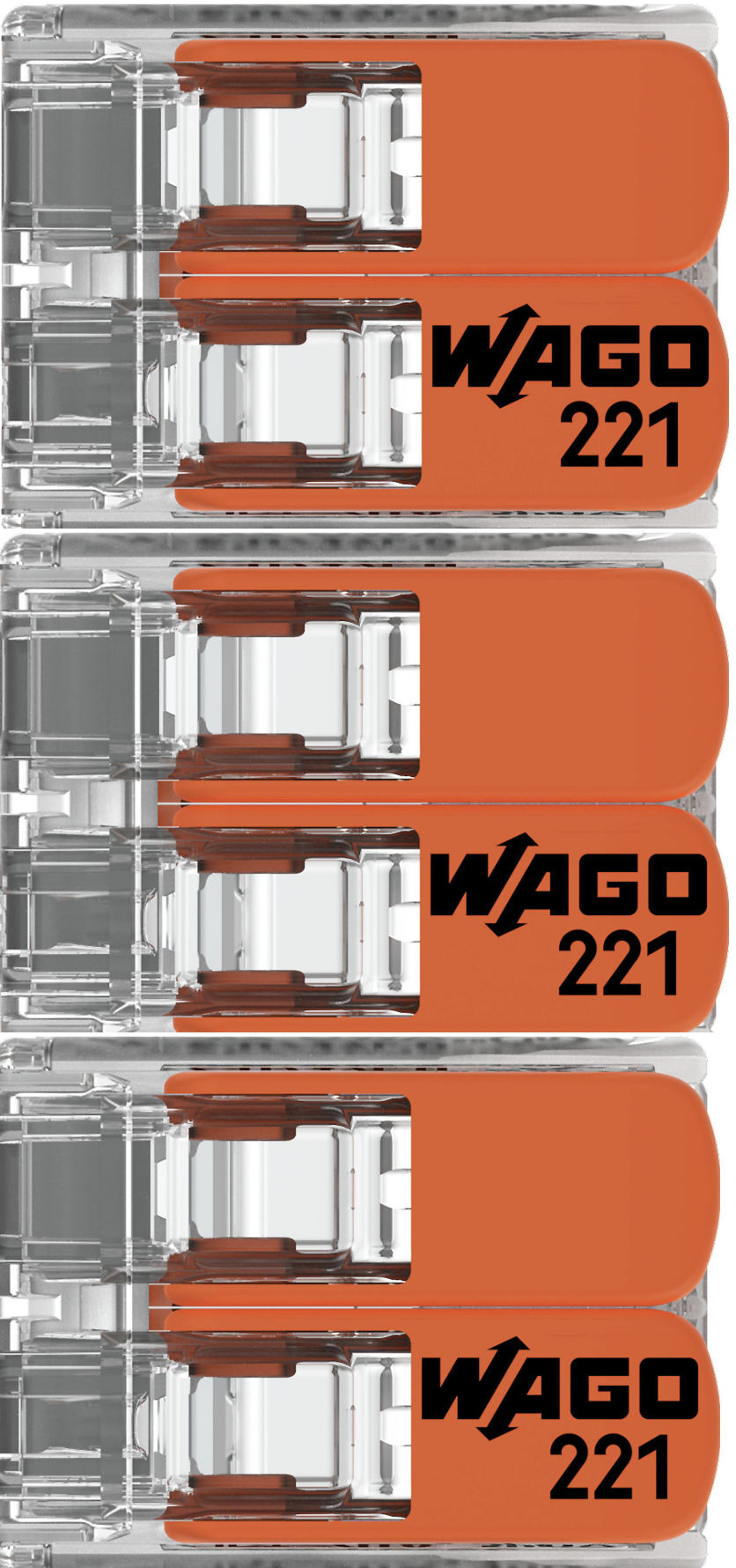
The Splicing Connector 6 by WAGO is a versatile electrical connector designed to join two or more wires securely and reliably. It simplifies the process of connecting wires in electrical circuits, offering a tool-free and reusable solution. This connector is particularly useful in applications where quick and safe wire connections are required, such as in lighting systems, control panels, and household wiring.
Explore Projects Built with splicing connector 6


Explore Projects Built with splicing connector 6
Common Applications and Use Cases
- Electrical wiring in residential, commercial, and industrial settings
- Connecting wires in lighting systems
- Use in control panels and distribution boxes
- Temporary or permanent wire connections in prototyping and testing
Technical Specifications
The following table outlines the key technical details of the Splicing Connector 6:
| Parameter | Specification |
|---|---|
| Manufacturer | WAGO |
| Part ID | Splicing Connector |
| Number of Connections | 6 |
| Wire Size Range | 28–12 AWG (0.08–4 mm²) |
| Voltage Rating | 450 V AC |
| Current Rating | 32 A |
| Operating Temperature | -35°C to +85°C |
| Housing Material | Polycarbonate (PC), flame-retardant |
| Contact Material | Copper alloy with tin plating |
| Certifications | UL, CE, RoHS compliant |
Pin Configuration and Descriptions
The Splicing Connector 6 does not have traditional pins but instead features six wire slots for connecting wires. The table below describes the slots:
| Slot Number | Description |
|---|---|
| 1–6 | Wire insertion points for connecting up to six wires |
| Test Slot | Dedicated slot for voltage testing without disconnecting |
Usage Instructions
How to Use the Splicing Connector 6 in a Circuit
- Prepare the Wires: Strip the insulation from the wires to expose 8–10 mm of the conductor.
- Open the Lever: Lift the lever on the splicing connector to open the wire slot.
- Insert the Wire: Insert the stripped wire into the slot until it reaches the stop.
- Close the Lever: Push the lever back down to secure the wire in place.
- Repeat: Repeat the process for all wires you wish to connect, using the remaining slots.
Important Considerations and Best Practices
- Ensure the wire is stripped to the correct length (8–10 mm) to avoid poor connections.
- Do not exceed the voltage or current ratings specified in the technical specifications.
- Use wires within the supported size range (28–12 AWG).
- For testing, use the dedicated test slot to measure voltage without disconnecting wires.
- Avoid exposing the connector to temperatures beyond its operating range (-35°C to +85°C).
Example: Connecting to an Arduino UNO
The Splicing Connector 6 can be used to connect multiple wires to an Arduino UNO for prototyping. For example, you can use it to distribute power from the Arduino's 5V and GND pins to multiple components.
// Example: Powering multiple LEDs using Splicing Connector 6
// Connect the Arduino's 5V and GND pins to the splicing connector.
// Then, connect the LEDs' positive and negative leads to the connector.

const int led1 = 2; // Pin for LED 1
const int led2 = 3; // Pin for LED 2
const int led3 = 4; // Pin for LED 3

void setup() {
  pinMode(led1, OUTPUT); // Set LED 1 pin as output
  pinMode(led2, OUTPUT); // Set LED 2 pin as output
  pinMode(led3, OUTPUT); // Set LED 3 pin as output
}

void loop() {
  digitalWrite(led1, HIGH); // Turn on LED 1
  digitalWrite(led2, HIGH); // Turn on LED 2
  digitalWrite(led3, HIGH); // Turn on LED 3
  delay(1000);              // Wait for 1 second

  digitalWrite(led1, LOW);  // Turn off LED 1
  digitalWrite(led2, LOW);  // Turn off LED 2
  digitalWrite(led3, LOW);  // Turn off LED 3
  delay(1000);              // Wait for 1 second
}
Troubleshooting and FAQs
Common Issues and Solutions
Loose Connections
- Cause: Wire not fully inserted or lever not properly closed.
- Solution: Ensure the wire is inserted to the stop and the lever is fully closed.
Overheating
- Cause: Exceeding the current rating of 32 A.
- Solution: Verify the current draw of the connected circuit and ensure it is within the specified limit.
Wire Slipping Out
- Cause: Incorrect wire size or improper stripping.
- Solution: Use wires within the supported size range (28–12 AWG) and strip them to the correct length (8–10 mm).
Difficulty in Testing Voltage
- Cause: Test probe not properly inserted into the test slot.
- Solution: Ensure the test probe is fully inserted into the dedicated test slot.
FAQs
Q: Can the Splicing Connector 6 be reused?
A: Yes, the connector is designed to be reusable. Simply lift the lever to release the wire and insert a new one.
Q: Is the connector suitable for outdoor use?
A: The connector is not waterproof. For outdoor use, ensure it is housed in a weatherproof enclosure.
Q: Can I connect wires of different sizes?
A: Yes, the connector supports wires of different sizes within the range of 28–12 AWG.
Q: How do I test the voltage without disconnecting wires?
A: Use the dedicated test slot to insert a voltage probe and measure the voltage safely.
This documentation provides all the necessary details to effectively use the WAGO Splicing Connector 6 in your projects.