How to Use Water Level Detection Module: Examples, Pinouts, and Specs
Introduction
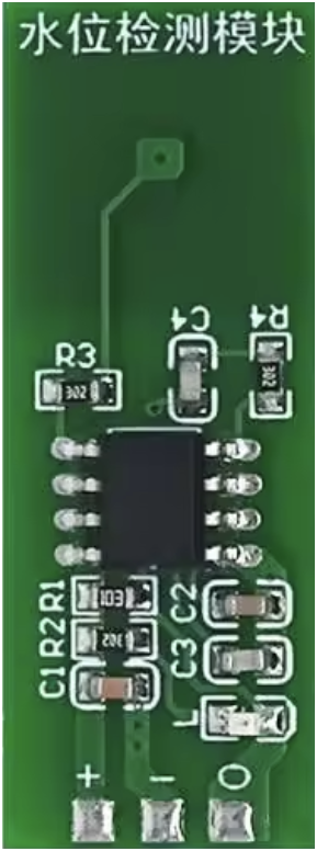
The Water Level Detection Module (ESP32 M04) is a versatile electronic component designed to monitor and detect water levels in tanks, reservoirs, or other liquid storage systems. It uses conductive or capacitive sensing technology to provide real-time data, making it ideal for automation and control applications. This module is widely used in smart home systems, industrial automation, agricultural irrigation, and water management systems.
Explore Projects Built with Water Level Detection Module
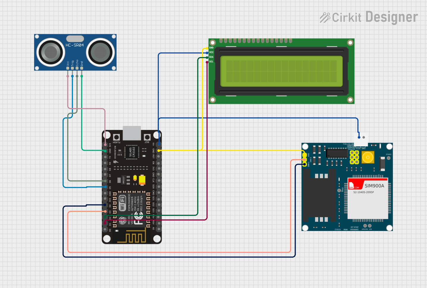
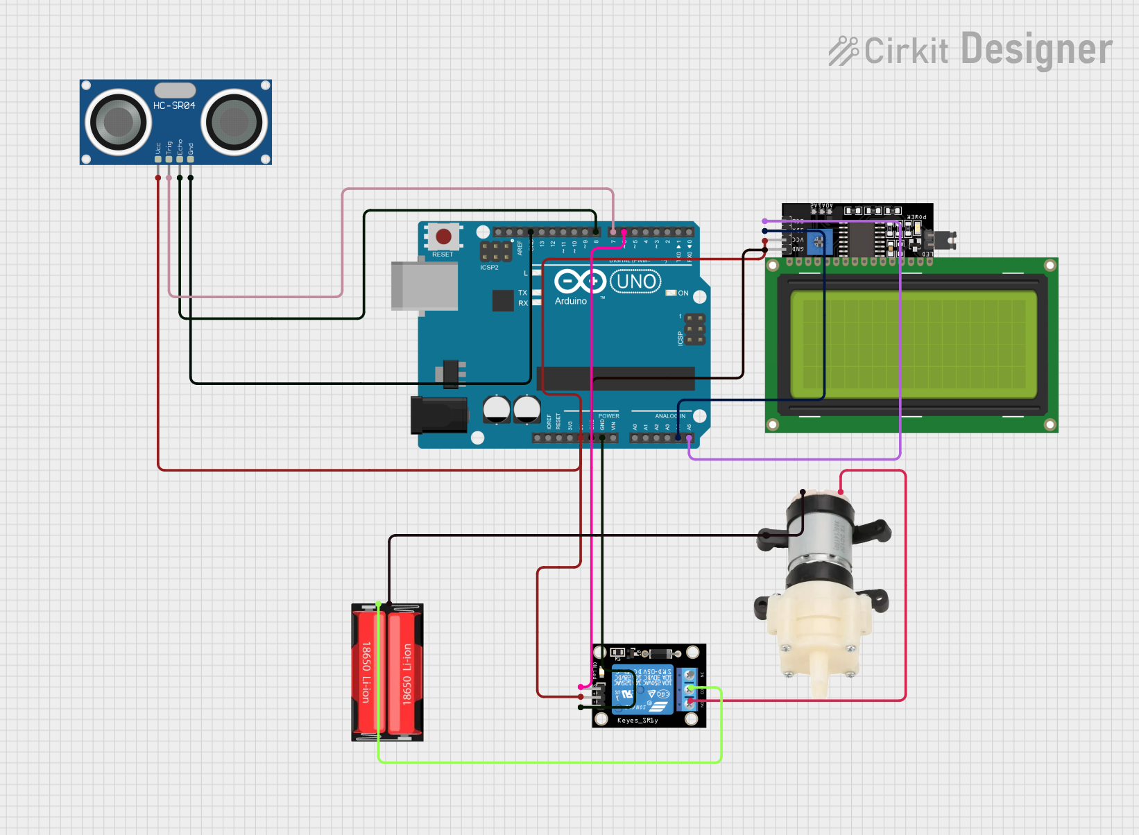
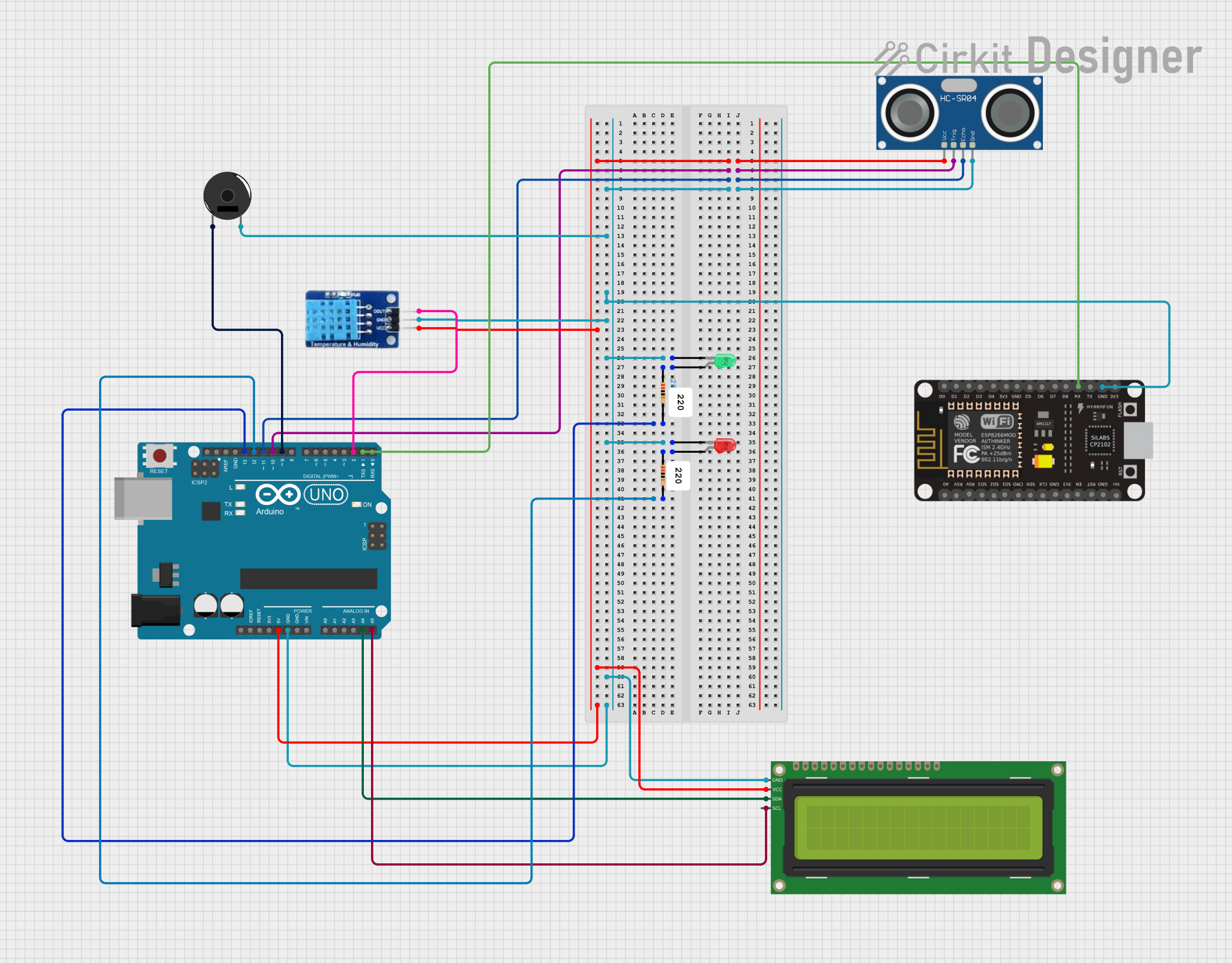

Explore Projects Built with Water Level Detection Module
Common Applications and Use Cases
- Monitoring water levels in household water tanks
- Automated irrigation systems for agriculture
- Industrial liquid level monitoring
- Flood detection and prevention systems
- Smart home automation for water usage optimization
Technical Specifications
The following table outlines the key technical details of the ESP32 M04 Water Level Detection Module:
| Parameter | Specification |
|---|---|
| Operating Voltage | 3.3V to 5V DC |
| Operating Current | ≤ 20mA |
| Output Type | Digital (High/Low) and Analog Output |
| Detection Range | 0 to 100% water level (adjustable) |
| Sensor Type | Capacitive or Conductive |
| Interface | 3-pin (VCC, GND, Signal) |
| Dimensions | 40mm x 20mm x 10mm |
| Operating Temperature | -10°C to 60°C |
Pin Configuration and Descriptions
The module has a simple 3-pin interface for easy integration into circuits. Below is the pin configuration:
| Pin | Name | Description |
|---|---|---|
| 1 | VCC | Power supply input (3.3V to 5V DC) |
| 2 | GND | Ground connection |
| 3 | Signal | Output pin providing water level data (digital HIGH/LOW or analog voltage level) |
Usage Instructions
How to Use the Component in a Circuit
- Power the Module: Connect the VCC pin to a 3.3V or 5V DC power source and the GND pin to the ground of your circuit.
- Connect the Signal Pin:
- For digital output, connect the Signal pin to a digital input pin on your microcontroller (e.g., ESP32 or Arduino UNO).
- For analog output, connect the Signal pin to an analog input pin to read water level percentages.
- Place the Sensor: Submerge the sensor in the water tank or reservoir. Ensure the sensor is properly positioned for accurate readings.
- Read the Output:
- A HIGH digital signal indicates water is detected.
- A LOW digital signal indicates no water is detected.
- For analog output, the voltage corresponds to the water level percentage.
Important Considerations and Best Practices
- Power Supply: Ensure the module is powered within the specified voltage range (3.3V to 5V DC).
- Sensor Placement: Avoid placing the sensor in areas with excessive turbulence or debris, as this may affect accuracy.
- Water Type: The module works best with clean water. For conductive sensors, avoid using in highly corrosive or saline water.
- Calibration: If the module supports calibration, adjust it according to the specific water level range of your application.
- Isolation: Use proper electrical isolation if the module is used in high-voltage or industrial environments.
Example Code for Arduino UNO
Below is an example code snippet to interface the Water Level Detection Module with an Arduino UNO:
// Define the pin connected to the Signal pin of the module
const int waterLevelPin = A0; // Use an analog pin for analog output
const int threshold = 500;   // Set a threshold for water detection (0-1023)

// Setup function to initialize the serial monitor and pin mode
void setup() {
  Serial.begin(9600);        // Start serial communication at 9600 baud
  pinMode(waterLevelPin, INPUT); // Set the water level pin as input
}

// Loop function to continuously read and display water level data
void loop() {
  int waterLevel = analogRead(waterLevelPin); // Read analog value from the module

  // Check if water level exceeds the threshold
  if (waterLevel > threshold) {
    Serial.println("Water detected!"); // Print message if water is detected
  } else {
    Serial.println("No water detected."); // Print message if no water is detected
  }

  delay(1000); // Wait for 1 second before the next reading
}
Troubleshooting and FAQs
Common Issues and Solutions
No Output Signal:
- Cause: Incorrect wiring or insufficient power supply.
- Solution: Double-check the connections and ensure the module is powered with 3.3V to 5V DC.
Inconsistent Readings:
- Cause: Sensor placement in turbulent or debris-filled water.
- Solution: Reposition the sensor in a stable and clean water environment.
Analog Output Not Working:
- Cause: Signal pin connected to a digital input pin.
- Solution: Connect the Signal pin to an analog input pin on the microcontroller.
Module Overheating:
- Cause: Operating the module outside the specified voltage range.
- Solution: Ensure the power supply voltage is within 3.3V to 5V DC.
FAQs
Q1: Can this module detect non-water liquids?
A1: The module is optimized for water detection. It may work with other liquids, but accuracy may vary depending on the liquid's conductivity or dielectric properties.
Q2: Is the module waterproof?
A2: The sensor is designed to be submerged, but the main module should be kept dry and protected from water exposure.
Q3: Can I use this module with an ESP32 microcontroller?
A3: Yes, the module is fully compatible with ESP32. Connect the Signal pin to an analog or digital input pin on the ESP32, depending on your application.
Q4: How do I extend the sensor's detection range?
A4: For capacitive sensors, you may need to use a larger sensing area. For conductive sensors, ensure proper placement and calibration.