How to Use 30A Motor Controller: Examples, Pinouts, and Specs
Introduction
A 30A Motor Controller is a robust electronic device engineered to manage the performance of motors by regulating the speed and direction of the electric current supplied to them. This component is essential in applications requiring precise motor control, such as in robotics, automation systems, electric vehicles, and various industrial processes. Its high current rating of 30 amperes makes it suitable for handling powerful motors that are used in demanding applications.
Explore Projects Built with 30A Motor Controller
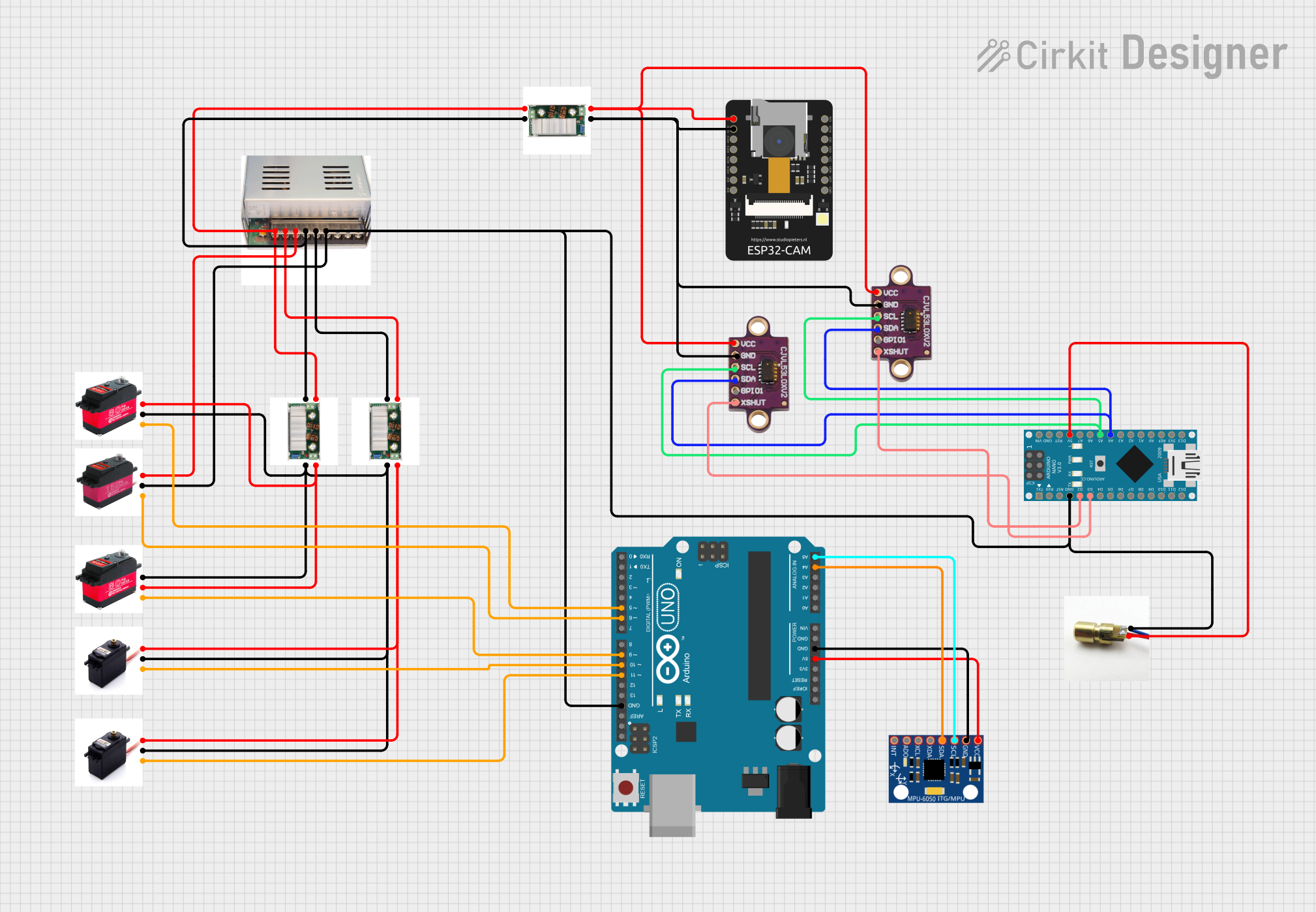

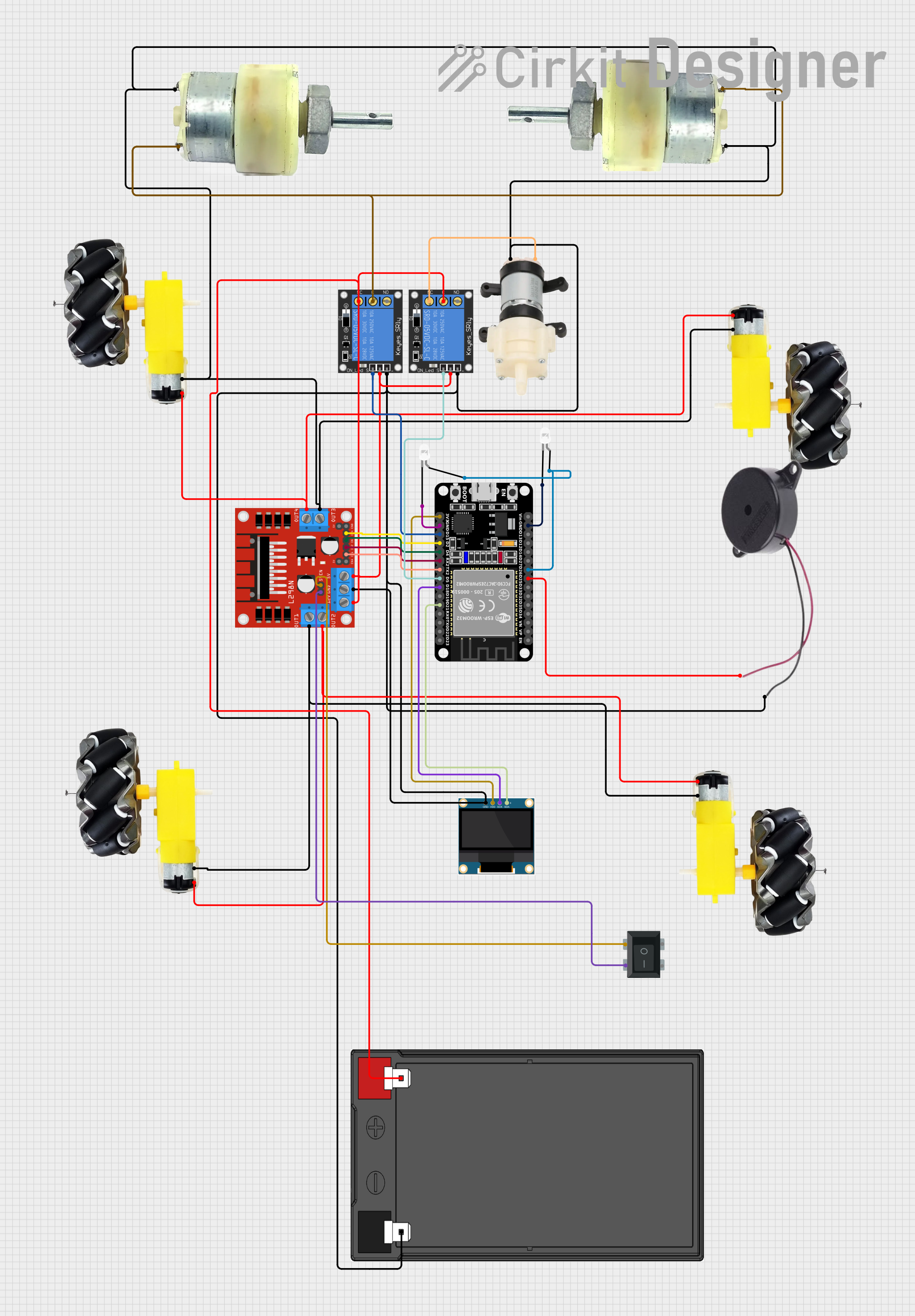

Explore Projects Built with 30A Motor Controller
Technical Specifications
General Features
- Current Rating: 30A continuous, up to 60A peak
- Voltage Range: 6V to 30V DC
- Control Method: PWM (Pulse Width Modulation)
- Direction Control: Bi-directional
- Protection Features: Overcurrent, thermal, and under-voltage protection
- Operating Temperature: -25°C to +85°C
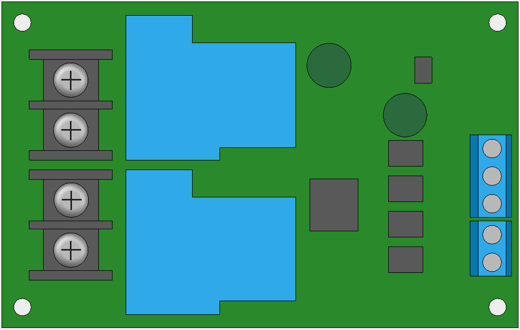
Pin Configuration and Descriptions
| Pin Number | Name | Description |
|---|---|---|
| 1 | V+ | Positive voltage supply input (6V to 30V DC) |
| 2 | GND | Ground connection |
| 3 | OUTA | Output A for motor connection |
| 4 | OUTB | Output B for motor connection |
| 5 | PWM | PWM signal input for speed control |
| 6 | DIR | Direction control input (logic level) |
| 7 | EN | Enable input (logic level) |
| 8 | CS | Current sensing output (analog voltage) |
Usage Instructions
Connecting the Motor Controller
- Power Supply: Connect a DC power supply to the V+ and GND pins, ensuring the voltage is within the specified range.
- Motor Connections: Attach the motor leads to OUTA and OUTB. The motor's polarity will determine the direction of rotation.
- Control Inputs: Connect the PWM, DIR, and EN pins to the respective outputs on your microcontroller or control circuitry.
- Current Sensing: Optionally, connect the CS pin to an analog input on your microcontroller to monitor the motor current.
Control Signal Details
- PWM Input: Apply a PWM signal to the PWM pin to control motor speed. The duty cycle of the PWM signal will determine the speed, with 0% being full stop and 100% being full speed.
- Direction Input: Apply a HIGH or LOW logic level to the DIR pin to control the direction of the motor.
- Enable Input: Apply a HIGH logic level to the EN pin to enable the motor controller. A LOW level will disable the controller, effectively stopping the motor.
Best Practices
- Always ensure the power supply voltage and motor current do not exceed the controller's specifications.
- Use a flyback diode across the motor terminals to protect against voltage spikes.
- Implement a proper cooling system if the controller is to be used near its maximum current rating.
- Use twisted-pair wires for the control signals to minimize electromagnetic interference.
Example Code for Arduino UNO
// Define the control pins
const int pwmPin = 3; // PWM input for speed control
const int dirPin = 4; // Direction control input
const int enPin = 5;  // Enable input

void setup() {
  // Set the control pins as outputs
  pinMode(pwmPin, OUTPUT);
  pinMode(dirPin, OUTPUT);
  pinMode(enPin, OUTPUT);

  // Enable the motor controller
  digitalWrite(enPin, HIGH);
}

void loop() {
  // Set the motor direction
  digitalWrite(dirPin, HIGH); // Set to LOW to reverse direction

  // Control the motor speed
  analogWrite(pwmPin, 128); // Set speed (0 to 255)

  // Add your code here to change direction or speed as needed
}
Troubleshooting and FAQs
Common Issues
- Motor not responding: Ensure all connections are secure and the power supply is within the specified range. Check that the EN pin is set HIGH to enable the controller.
- Motor spinning in one direction only: Verify the DIR pin is being toggled correctly and that the control signal is within the correct logic level range.
- Overheating: If the controller is overheating, reduce the load or improve cooling. Ensure the ambient temperature is within the operating range.
FAQs
Q: Can I control two motors with this controller? A: This controller is designed for a single motor. To control two motors, you would need two controllers or a dual-channel motor controller.
Q: What is the maximum PWM frequency that can be used? A: The maximum PWM frequency depends on the specific motor controller model. Refer to the datasheet for the exact value, but typically it is around 20kHz.
Q: How do I reverse the motor direction? A: To reverse the motor direction, change the logic level on the DIR pin.
Q: Can I use this controller with a 24V motor? A: Yes, as long as the motor's current does not exceed 30A and the voltage does not exceed the controller's maximum rating.
Q: How can I implement a soft start for the motor? A: Gradually increase the PWM duty cycle from 0% to the desired speed over a period of time to achieve a soft start.
For further assistance, consult the manufacturer's datasheet or contact technical support.