Cirkit Designer Logo
Cirkit Designer
Your all-in-one circuit design IDE
Home / 
Component Documentation

How to Use Adafruit Feather 32u4 Adalogger: Examples, Pinouts, and Specs

Image of Adafruit Feather 32u4 Adalogger
Cirkit Designer LogoDesign with Adafruit Feather 32u4 Adalogger in Cirkit Designer

Introduction

The Adafruit Feather 32u4 Adalogger is a versatile and portable development board that combines the power of the ATmega32u4 microcontroller with the convenience of an onboard microSD card slot for data logging. This board is part of the Feather ecosystem, designed by Adafruit for ease of use and flexibility. It is ideal for projects that require data collection, such as environmental monitoring, experimental data logging, or even as a tiny, stand-alone GPS logger.

Explore Projects Built with Adafruit Feather 32u4 Adalogger

Use Cirkit Designer to design, explore, and prototype these projects online. Some projects support real-time simulation. Click "Open Project" to start designing instantly!
ESP32-Based Vibration Feedback System with Quad Alphanumeric Display and ADXL343 Accelerometer
Image of EC444 - Quest 3: A project utilizing Adafruit Feather 32u4 Adalogger in a practical application
This circuit features an Adafruit HUZZAH32 ESP32 Feather board as the central microcontroller, which is connected to an Adafruit Quad AlphaNumeric Featherwing display and an Adafruit ADXL343 accelerometer via I2C communication (SCL and SDA lines). The ESP32 controls a vibration motor connected to one of its GPIO pins (A5_IO4) and shares a common power supply (3.3V) and ground (GND) with the other components. The purpose of this circuit is likely to read acceleration data, display information on the alphanumeric display, and provide haptic feedback through the vibration motor.
Cirkit Designer LogoOpen Project in Cirkit Designer
Multi-Sensor Health Monitoring System with Adafruit Feather M0 Adalogger
Image of health tracker: A project utilizing Adafruit Feather 32u4 Adalogger in a practical application
This circuit is designed to interface multiple sensors with an Adafruit Feather M0 Adalogger microcontroller for data logging purposes. The sensors include a MAX30205 temperature sensor, a body dehydration sensor, a MAX30102 pulse oximeter, an Adafruit LSM6DSOX 6-axis accelerometer and gyroscope, and an Adafruit BME680 environmental sensor. All sensors are connected to the microcontroller via an I2C bus, sharing the SDA and SCL lines for communication.
Cirkit Designer LogoOpen Project in Cirkit Designer
Battery-Powered ESP32 Temperature Monitoring System
Image of Temp Sensor: A project utilizing Adafruit Feather 32u4 Adalogger in a practical application
This circuit consists of an Adafruit HUZZAH32 ESP32 Feather microcontroller, a temperature sensor, and a battery. The ESP32 reads temperature data from the sensor and is powered by the battery, enabling wireless temperature monitoring.
Cirkit Designer LogoOpen Project in Cirkit Designer
Solar-Powered Environmental Data Logger with Adafruit Feather M0 Express
Image of Lake Thoreau Monitoring Station: A project utilizing Adafruit Feather 32u4 Adalogger in a practical application
This circuit is designed for environmental data collection and logging, utilizing an Adafruit Feather M0 Express microcontroller as the central processing unit. It interfaces with a BME280 sensor for atmospheric temperature, humidity, and pressure measurements, an SGP30 sensor for monitoring air quality (eCO2 and TVOC), and a STEMMA soil sensor for detecting soil moisture and temperature. The system is powered by a solar panel and a 3.7v LiPo battery, managed by an Adafruit BQ24074 Solar-DC-USB Lipo Charger, and provides easy access to the microcontroller's connections through an Adafruit Terminal Breakout FeatherWing.
Cirkit Designer LogoOpen Project in Cirkit Designer

Explore Projects Built with Adafruit Feather 32u4 Adalogger

Use Cirkit Designer to design, explore, and prototype these projects online. Some projects support real-time simulation. Click "Open Project" to start designing instantly!
Image of EC444 - Quest 3: A project utilizing Adafruit Feather 32u4 Adalogger in a practical application
ESP32-Based Vibration Feedback System with Quad Alphanumeric Display and ADXL343 Accelerometer
This circuit features an Adafruit HUZZAH32 ESP32 Feather board as the central microcontroller, which is connected to an Adafruit Quad AlphaNumeric Featherwing display and an Adafruit ADXL343 accelerometer via I2C communication (SCL and SDA lines). The ESP32 controls a vibration motor connected to one of its GPIO pins (A5_IO4) and shares a common power supply (3.3V) and ground (GND) with the other components. The purpose of this circuit is likely to read acceleration data, display information on the alphanumeric display, and provide haptic feedback through the vibration motor.
Cirkit Designer LogoOpen Project in Cirkit Designer
Image of health tracker: A project utilizing Adafruit Feather 32u4 Adalogger in a practical application
Multi-Sensor Health Monitoring System with Adafruit Feather M0 Adalogger
This circuit is designed to interface multiple sensors with an Adafruit Feather M0 Adalogger microcontroller for data logging purposes. The sensors include a MAX30205 temperature sensor, a body dehydration sensor, a MAX30102 pulse oximeter, an Adafruit LSM6DSOX 6-axis accelerometer and gyroscope, and an Adafruit BME680 environmental sensor. All sensors are connected to the microcontroller via an I2C bus, sharing the SDA and SCL lines for communication.
Cirkit Designer LogoOpen Project in Cirkit Designer
Image of Temp Sensor: A project utilizing Adafruit Feather 32u4 Adalogger in a practical application
Battery-Powered ESP32 Temperature Monitoring System
This circuit consists of an Adafruit HUZZAH32 ESP32 Feather microcontroller, a temperature sensor, and a battery. The ESP32 reads temperature data from the sensor and is powered by the battery, enabling wireless temperature monitoring.
Cirkit Designer LogoOpen Project in Cirkit Designer
Image of Lake Thoreau Monitoring Station: A project utilizing Adafruit Feather 32u4 Adalogger in a practical application
Solar-Powered Environmental Data Logger with Adafruit Feather M0 Express
This circuit is designed for environmental data collection and logging, utilizing an Adafruit Feather M0 Express microcontroller as the central processing unit. It interfaces with a BME280 sensor for atmospheric temperature, humidity, and pressure measurements, an SGP30 sensor for monitoring air quality (eCO2 and TVOC), and a STEMMA soil sensor for detecting soil moisture and temperature. The system is powered by a solar panel and a 3.7v LiPo battery, managed by an Adafruit BQ24074 Solar-DC-USB Lipo Charger, and provides easy access to the microcontroller's connections through an Adafruit Terminal Breakout FeatherWing.
Cirkit Designer LogoOpen Project in Cirkit Designer

Common Applications and Use Cases

  • Environmental data logging (temperature, humidity, pressure)
  • GPS tracking and logging
  • Wearable devices
  • Educational projects and prototyping
  • IoT and smart home devices

Technical Specifications

Key Technical Details

  • Microcontroller: ATmega32u4
  • Operating Voltage: 3.3V
  • Input Voltage: 3.7-6V via battery and up to 12V via the USB or VIN pin
  • Clock Speed: 8 MHz
  • Digital I/O Pins: 20
  • PWM Channels: 7
  • Analog Input Channels: 12
  • DC Current per I/O Pin: 40 mA
  • Flash Memory: 32 KB (ATmega32u4) of which 4 KB used by bootloader
  • SRAM: 2.5 KB (ATmega32u4)
  • EEPROM: 1 KB (ATmega32u4)
  • MicroSD card slot for data logging

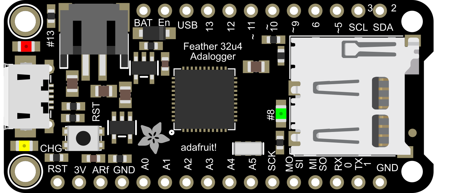
Pin Configuration and Descriptions

Pin Number Function Description
1 GND Ground
2 BAT Battery +
3 EN Enable pin for the 3.3V regulator
4 USB USB data-
5 USB USB data+
6-13 Digital I/O Digital pins, can also serve as PWM, SPI, I2C
14-19 Analog Input Analog pins, can also serve as digital I/O
20 AREF Analog reference voltage for the ADC
21 SCK SPI clock
22 MISO SPI Master In Slave Out
23 MOSI SPI Master Out Slave In
24 SS SPI Slave Select
25 RXLED RX LED, lights up when the USB port receives data
26 TXLED TX LED, lights up when the USB port sends data
27 SDA I2C Data
28 SCL I2C Clock
29 RST Reset pin

Usage Instructions

How to Use the Component in a Circuit

  1. Powering the Adalogger: You can power the Adalogger through the USB connection, a LiPo battery, or an external power supply connected to the VIN pin.
  2. Connecting Sensors: Use the digital and analog pins to connect sensors. Ensure that the sensors are compatible with the 3.3V logic level.
  3. Data Logging: Insert a formatted microSD card into the slot. Use the onboard SD library to write data to the card.
  4. Programming: The board is programmable via the Arduino IDE. Select "Adafruit Feather 32u4" from the Boards menu.

Important Considerations and Best Practices

  • Always ensure that the power supply is within the specified range to prevent damage.
  • When using the microSD card slot, make sure the card is formatted correctly (FAT16 or FAT32).
  • Disconnect the battery when programming the board via USB to avoid power conflicts.
  • Use a regulated 3.3V supply when connecting external components to prevent damage to the board.

Example Code for Arduino UNO

#include <SPI.h>
#include <SD.h>

File dataFile;

void setup() {
  // Open serial communications and wait for port to open:
  Serial.begin(9600);
  while (!Serial) {
    ; // Wait for serial port to connect. Needed for native USB port only
  }

  Serial.print("Initializing SD card...");

  if (!SD.begin(4)) { // Make sure to use the correct chip select pin
    Serial.println("initialization failed!");
    return;
  }
  Serial.println("initialization done.");

  // Create or open the data file
  dataFile = SD.open("datalog.txt", FILE_WRITE);

  // If the file is available, write to it:
  if (dataFile) {
    dataFile.println("Logging data...");
    dataFile.close(); // Make sure to close the file when you're done
    Serial.println("Data written.");
  } else {
    // If the file isn't open, pop up an error:
    Serial.println("error opening datalog.txt");
  }
}

void loop() {
  // Nothing here for now.
}

Troubleshooting and FAQs

Common Issues Users Might Face

  • SD Card Not Recognized: Ensure the card is properly inserted and formatted to FAT16 or FAT32.
  • Board Not Detected by Computer: Check the USB cable and drivers. Press the reset button twice quickly to enter bootloader mode.
  • Inaccurate Sensor Readings: Verify that the sensor is compatible with 3.3V logic and is connected correctly.

Solutions and Tips for Troubleshooting

  • If the SD card is not working, try using another card or reformatting the existing one.
  • For driver issues, ensure you have the latest drivers installed for the board.
  • Double-check all connections and solder joints for continuity and shorts.
  • Consult the Adafruit forums and guides for additional support.

FAQs

Q: Can I power the Adalogger with a 5V supply? A: No, the operating voltage is 3.3V. You must use a regulated 3.3V supply or the onboard USB connection.

Q: How do I program the Adalogger? A: You can program it using the Arduino IDE. Select the "Adafruit Feather 32u4" board from the Boards menu.

Q: What is the maximum size of the SD card that can be used? A: The Adalogger supports microSD cards up to 32GB in size.

Q: Can I use the Adalogger for real-time clock (RTC) applications? A: Yes, the Adalogger has a built-in RTC. You'll need to add a 3V coin cell battery to the board to keep the clock running when power is disconnected.