Cirkit Designer Logo
Cirkit Designer
Your all-in-one circuit design IDE
Home / 
Component Documentation

How to Use inductive sensor: Examples, Pinouts, and Specs

Image of inductive sensor
Cirkit Designer LogoDesign with inductive sensor in Cirkit Designer

Introduction

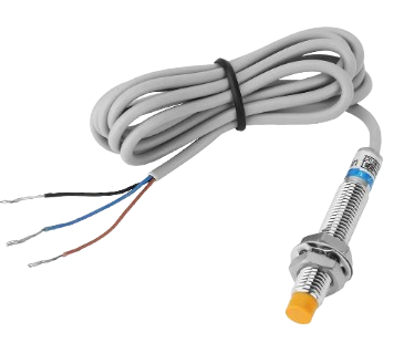
An inductive sensor is a non-contact electronic proximity sensor that is used to detect the presence of metal objects without requiring physical contact. It operates on the principle of inductance, which is the property of an electrical conductor to induce a voltage in itself or in any nearby conductors due to a change in the magnetic field.

Explore Projects Built with inductive sensor

Use Cirkit Designer to design, explore, and prototype these projects online. Some projects support real-time simulation. Click "Open Project" to start designing instantly!
Arduino Nano Controlled Inductive Sensor with OLED Display
Image of Digital RPM Sensor: A project utilizing inductive sensor in a practical application
This circuit features an Arduino Nano microcontroller interfaced with a 0.96" OLED display and an inductive sensor. The Arduino Nano provides power to both the OLED and the sensor, and communicates with the OLED via I2C (using A4 for SDA and A5 for SCK). The inductive sensor is connected to the A3 pin of the Arduino, likely for sensing metallic objects and sending the signal back to the microcontroller for processing.
Cirkit Designer LogoOpen Project in Cirkit Designer
Arduino-Controlled Servo System with Inductive and Capacitive Sensors
Image of ISTG: A project utilizing inductive sensor in a practical application
This is a sensor-actuator system where an Arduino UNO controls four servomotors based on inputs from an inductive and a capacitive sensor. The servomotors are likely used for precise positioning or movement, while the sensors detect proximity or touch, enabling interactive or automated responses.
Cirkit Designer LogoOpen Project in Cirkit Designer
Arduino UNO-Based Inductive Sensor and 7-Segment Display System
Image of comarch: A project utilizing inductive sensor in a practical application
This circuit uses an Arduino UNO to read signals from an inductive sensor and display the results on a 7-segment display. The inductive sensor is powered by the Arduino and its signal is connected to a digital input pin, while the 7-segment display is driven by the Arduino through a series of digital output pins and a current-limiting resistor.
Cirkit Designer LogoOpen Project in Cirkit Designer
Arduino UNO-Based Smart Robotic System with IR Sensors and Motor Control
Image of SEGREGATOR: A project utilizing inductive sensor in a practical application
This circuit is a sensor-based control system using an Arduino UNO, which interfaces with multiple IR sensors, a capacitive sensor, an inductive sensor, and controls a motor and servos via an L298N motor driver. The system also includes a piezo buzzer for audio feedback and is powered by a 12V battery with a buck converter to step down the voltage for the sensors and servos.
Cirkit Designer LogoOpen Project in Cirkit Designer

Explore Projects Built with inductive sensor

Use Cirkit Designer to design, explore, and prototype these projects online. Some projects support real-time simulation. Click "Open Project" to start designing instantly!
Image of Digital RPM Sensor: A project utilizing inductive sensor in a practical application
Arduino Nano Controlled Inductive Sensor with OLED Display
This circuit features an Arduino Nano microcontroller interfaced with a 0.96" OLED display and an inductive sensor. The Arduino Nano provides power to both the OLED and the sensor, and communicates with the OLED via I2C (using A4 for SDA and A5 for SCK). The inductive sensor is connected to the A3 pin of the Arduino, likely for sensing metallic objects and sending the signal back to the microcontroller for processing.
Cirkit Designer LogoOpen Project in Cirkit Designer
Image of ISTG: A project utilizing inductive sensor in a practical application
Arduino-Controlled Servo System with Inductive and Capacitive Sensors
This is a sensor-actuator system where an Arduino UNO controls four servomotors based on inputs from an inductive and a capacitive sensor. The servomotors are likely used for precise positioning or movement, while the sensors detect proximity or touch, enabling interactive or automated responses.
Cirkit Designer LogoOpen Project in Cirkit Designer
Image of comarch: A project utilizing inductive sensor in a practical application
Arduino UNO-Based Inductive Sensor and 7-Segment Display System
This circuit uses an Arduino UNO to read signals from an inductive sensor and display the results on a 7-segment display. The inductive sensor is powered by the Arduino and its signal is connected to a digital input pin, while the 7-segment display is driven by the Arduino through a series of digital output pins and a current-limiting resistor.
Cirkit Designer LogoOpen Project in Cirkit Designer
Image of SEGREGATOR: A project utilizing inductive sensor in a practical application
Arduino UNO-Based Smart Robotic System with IR Sensors and Motor Control
This circuit is a sensor-based control system using an Arduino UNO, which interfaces with multiple IR sensors, a capacitive sensor, an inductive sensor, and controls a motor and servos via an L298N motor driver. The system also includes a piezo buzzer for audio feedback and is powered by a 12V battery with a buck converter to step down the voltage for the sensors and servos.
Cirkit Designer LogoOpen Project in Cirkit Designer

Common Applications and Use Cases

  • Industrial automation and robotics
  • Position sensing
  • Metal object detection
  • Revolution counting
  • Speed monitoring

Technical Specifications

Key Technical Details

  • Supply Voltage (Vcc): Typically 6-36V DC
  • Output Current: Usually up to 200 mA
  • Sensing Distance: Varies, typically 1-20 mm depending on the sensor size and the target material
  • Frequency: Can range from a few Hz to several kHz
  • Operating Temperature: -25°C to +70°C (may vary by model)

Pin Configuration and Descriptions

Pin Number Description Notes
1 Vcc (Power Supply) Connect to positive power supply
2 Output Switching signal (NPN/PNP)
3 Ground (GND) Connect to system ground

Usage Instructions

How to Use the Component in a Circuit

  1. Power Supply: Connect the Vcc pin to a DC power supply within the sensor's specified voltage range.
  2. Grounding: Connect the GND pin to the ground of the power supply and your control system.
  3. Output Signal: Connect the output pin to the input of your control system (e.g., PLC, microcontroller).

Important Considerations and Best Practices

  • Ensure that the metal target is within the specified sensing range.
  • Avoid placing the sensor near large metal surfaces that may interfere with the magnetic field.
  • Use shielded cables to minimize electromagnetic interference (EMI).
  • Do not exceed the voltage and current ratings to prevent damage to the sensor.

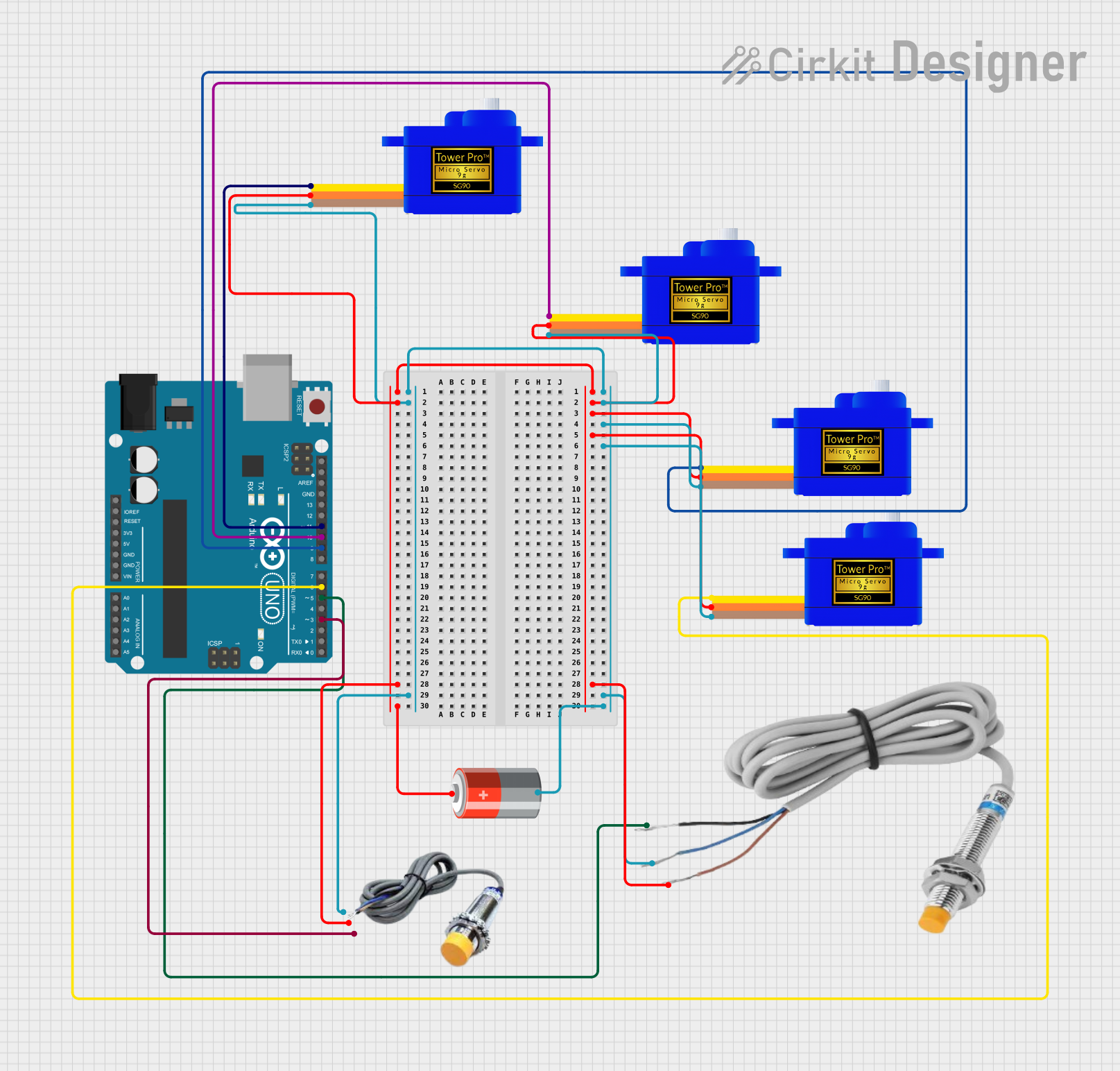
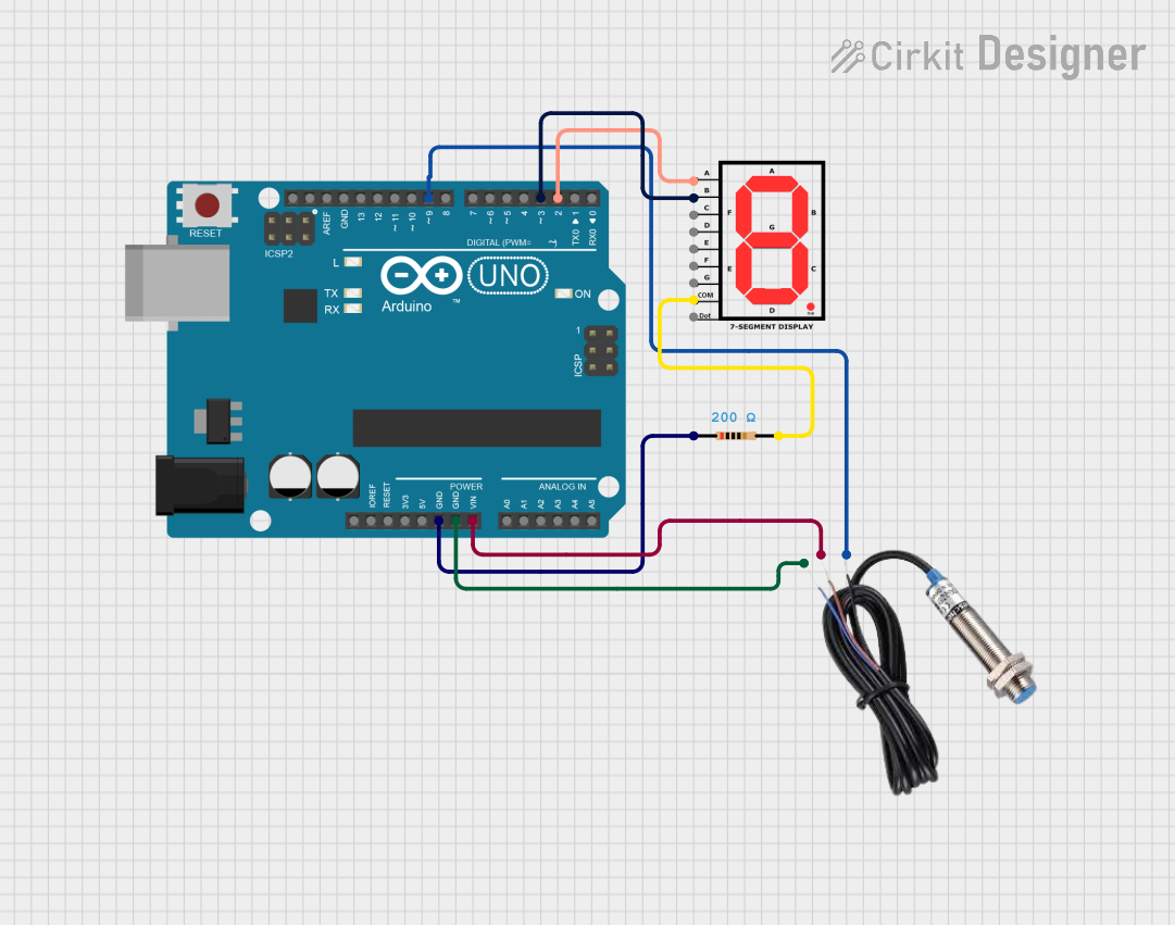
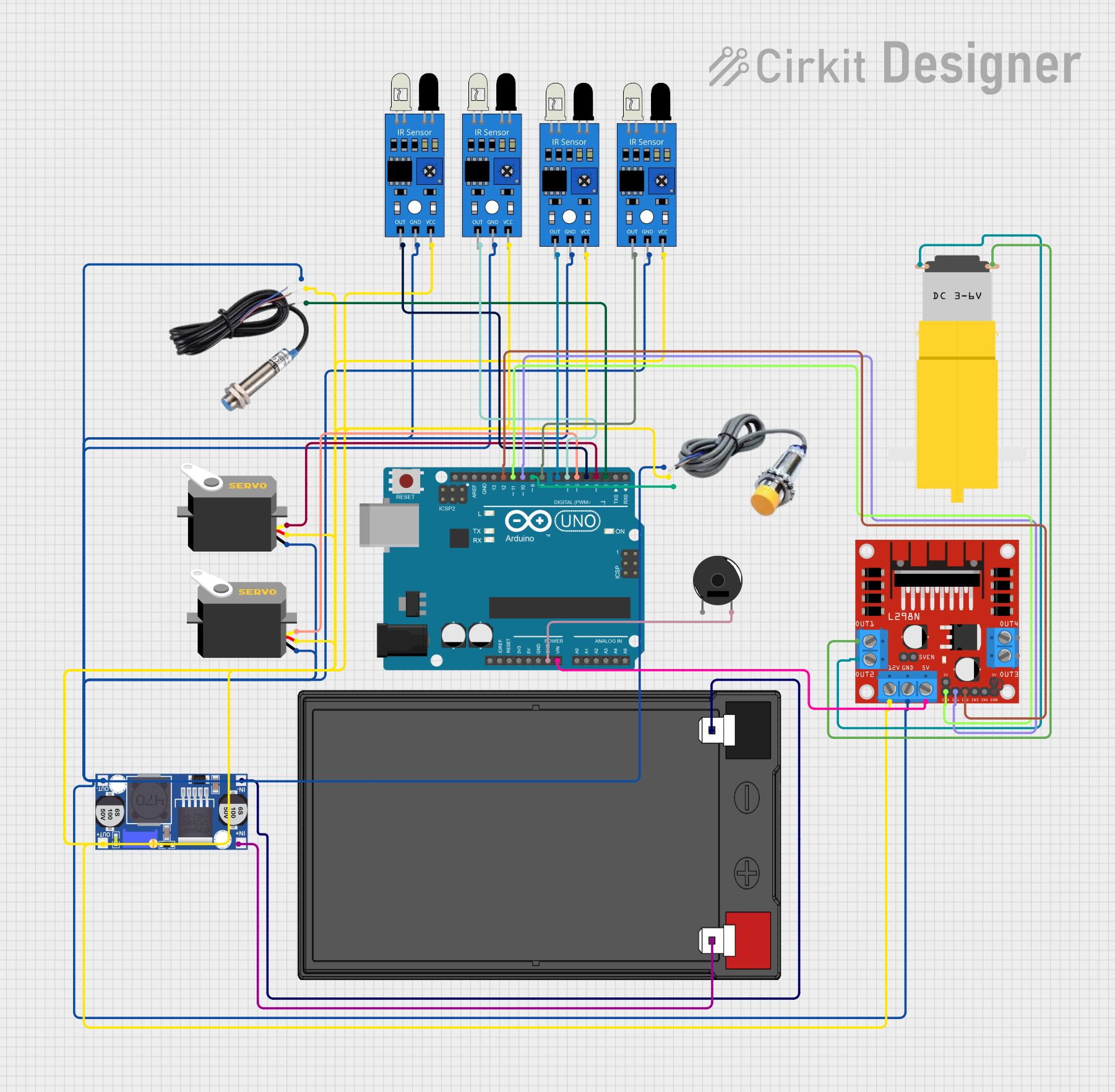
Example Connection with Arduino UNO

// Define the sensor output pin connected to the Arduino
const int inductiveSensorPin = 2; // Digital pin 2

void setup() {
  // Set the sensor pin as an input
  pinMode(inductiveSensorPin, INPUT);
  // Begin serial communication at 9600 baud rate
  Serial.begin(9600);
}

void loop() {
  // Read the sensor state (HIGH when metal is detected)
  int sensorState = digitalRead(inductiveSensorPin);
  
  // Print the sensor state to the Serial Monitor
  Serial.println(sensorState);
  delay(100); // Delay for stability
}

Troubleshooting and FAQs

Common Issues Users Might Face

  • Sensor not detecting metal: Check if the metal object is within the sensing range and the sensor is properly powered.
  • False triggering: Ensure there are no unintended metal objects within the sensing range and check for EMI sources.
  • No output signal: Verify connections, ensure the power supply is within the specified range, and check the sensor's LED indicator if available.

Solutions and Tips for Troubleshooting

  • Use a multimeter to check for proper voltage levels at the sensor's power supply and output pins.
  • Reorient or relocate the sensor to minimize interference from other metal objects or EMI sources.
  • Check the manufacturer's datasheet for specific troubleshooting steps related to your sensor model.

FAQs

Q: Can inductive sensors detect non-metal objects? A: No, inductive sensors are designed to detect metal objects only.

Q: What is the difference between NPN and PNP output? A: NPN (sinking) outputs connect to ground when activated, while PNP (sourcing) outputs connect to the power supply when activated. Choose based on your control system requirements.

Q: How can I extend the sensing range of my inductive sensor? A: The sensing range is fixed based on the sensor design. Using a larger sensor or one specifically designed for a greater range is necessary to detect objects from further away.

Q: Are inductive sensors affected by water or dust? A: Inductive sensors are typically enclosed in a robust housing making them suitable for harsh environments, but always check the IP rating for specifics on water and dust resistance.