
How to Use SparkFun NEO-M9N GNSS breakou: Examples, Pinouts, and Specs
 Design with SparkFun NEO-M9N GNSS breakou in Cirkit Designer
Introduction
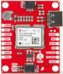
The SparkFun NEO-M9N GNSS Breakout is a compact and versatile GPS module designed to provide high-precision positioning data. Powered by the u-blox NEO-M9N chip, this module supports multiple Global Navigation Satellite Systems (GNSS), including GPS, GLONASS, Galileo, and BeiDou. It is ideal for applications requiring accurate location tracking, such as robotics, drones, IoT devices, and geolocation-based projects.
Explore Projects Built with SparkFun NEO-M9N GNSS breakou
 Open Project in Cirkit Designer
 Open Project in Cirkit Designer
 Open Project in Cirkit Designer
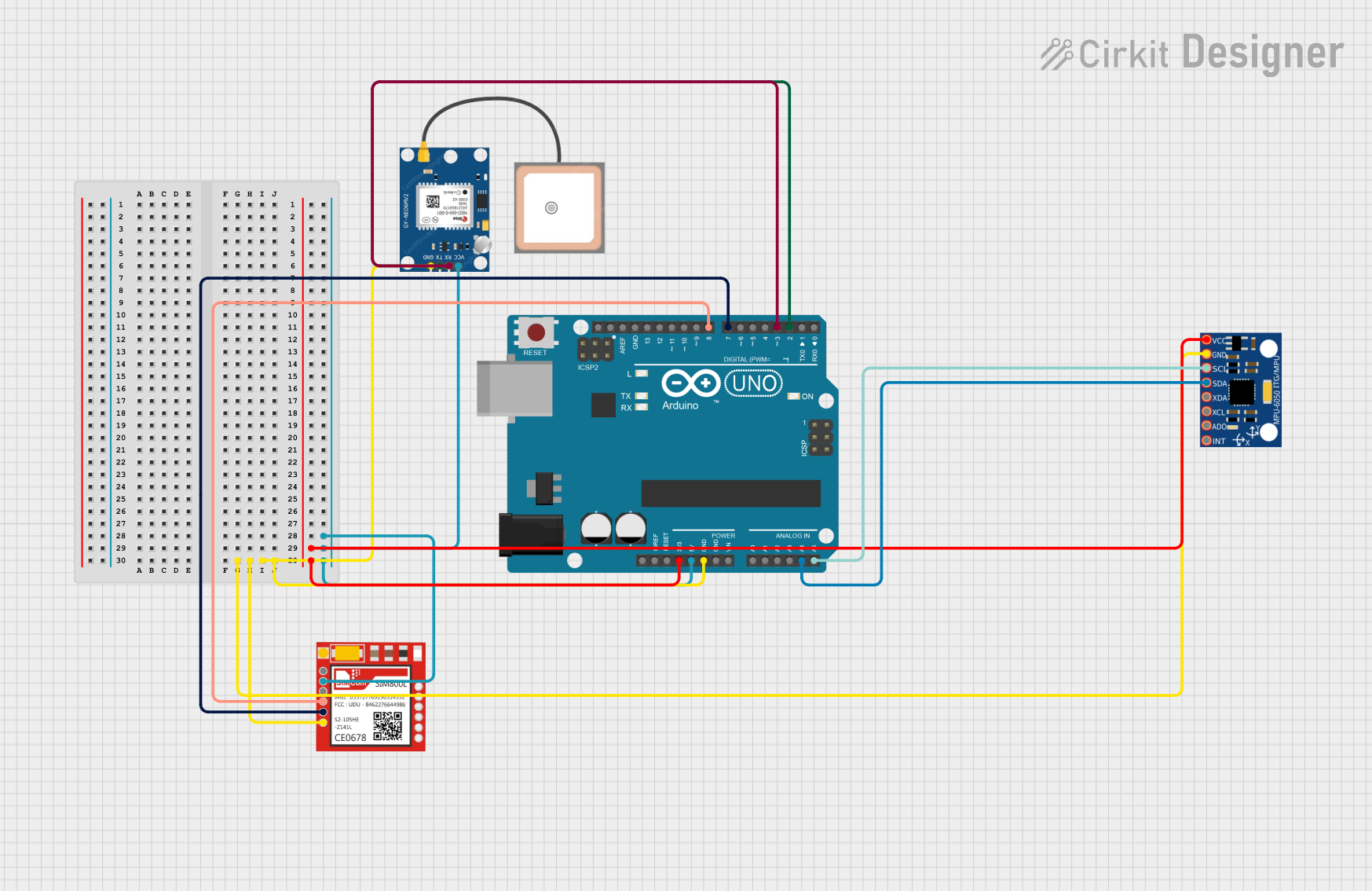 Open Project in Cirkit Designer
Explore Projects Built with SparkFun NEO-M9N GNSS breakou
Open Project in Cirkit DesignerOpen Project in Cirkit DesignerOpen Project in Cirkit DesignerOpen Project in Cirkit DesignerCommon Applications and Use Cases
- Autonomous vehicles and drones
- Geographic Information Systems (GIS)
- IoT devices requiring location data
- Navigation systems
- Timing and synchronization in networks
Technical Specifications
The following table outlines the key technical details of the SparkFun NEO-M9N GNSS Breakout:
| Parameter | Specification |
|---|---|
| Chipset | u-blox NEO-M9N |
| GNSS Systems Supported | GPS, GLONASS, Galileo, BeiDou |
| Frequency Bands | L1/E1/B1 |
| Position Accuracy | 1.5 meters (CEP) |
| Update Rate | Up to 25 Hz |
| Input Voltage | 3.3V (recommended), 5V tolerant |
| Power Consumption | ~23 mA (typical) |
| Communication Interfaces | UART, I2C, SPI |
| Operating Temperature | -40°C to +85°C |
| Dimensions | 25.4 mm x 25.4 mm |
Pin Configuration and Descriptions
The SparkFun NEO-M9N GNSS Breakout features the following pinout:
| Pin Name | Type | Description |
|---|---|---|
| GND | Power | Ground connection |
| 3.3V | Power | 3.3V power input |
| RX | Input | UART receive pin (for communication with a microcontroller) |
| TX | Output | UART transmit pin (for communication with a microcontroller) |
| SCL | Input | I2C clock line |
| SDA | Input/Output | I2C data line |
| CS | Input | SPI chip select |
| MISO | Output | SPI Master In Slave Out |
| MOSI | Input | SPI Master Out Slave In |
| SCK | Input | SPI clock |
| PPS | Output | Pulse Per Second signal for timing applications |
| RST | Input | Reset pin |
Usage Instructions
How to Use the Component in a Circuit
- Power Supply: Connect the
3.3Vpin to a 3.3V power source and theGNDpin to ground. The module is 5V tolerant, but 3.3V is recommended for optimal performance. - Communication Interface: Choose one of the supported communication interfaces (UART, I2C, or SPI) based on your application:
- For UART, connect the
RXandTXpins to the corresponding pins on your microcontroller. - For I2C, connect the
SCLandSDApins to the I2C bus of your microcontroller. - For SPI, connect the
CS,MISO,MOSI, andSCKpins to the SPI bus of your microcontroller.
- For UART, connect the
- Antenna: Attach an active or passive antenna to the u.FL connector on the breakout board for optimal satellite reception.
- Optional Connections: Use the
PPSpin for timing applications or theRSTpin to reset the module if needed.
Important Considerations and Best Practices
- Ensure the antenna has a clear view of the sky for optimal satellite reception.
- Use decoupling capacitors near the power supply pins to reduce noise.
- Avoid placing the module near high-frequency noise sources, such as switching regulators or Wi-Fi modules.
- If using I2C, ensure pull-up resistors are present on the
SCLandSDAlines.
Example Code for Arduino UNO
Below is an example of how to interface the SparkFun NEO-M9N GNSS Breakout with an Arduino UNO using the UART interface:
#include <SoftwareSerial.h>

// Define RX and TX pins for SoftwareSerial
SoftwareSerial gpsSerial(4, 3); // RX = Pin 4, TX = Pin 3

void setup() {
  Serial.begin(9600); // Initialize Serial Monitor
  gpsSerial.begin(9600); // Initialize GPS module communication

  Serial.println("SparkFun NEO-M9N GNSS Breakout Example");
}

void loop() {
  // Check if data is available from the GPS module
  while (gpsSerial.available()) {
    char c = gpsSerial.read(); // Read a character from the GPS module
    Serial.print(c); // Print the character to the Serial Monitor
  }
}
Note: Install the u-blox library or any relevant GNSS library for advanced functionality.
Troubleshooting and FAQs
Common Issues and Solutions
No GPS Fix:
- Ensure the antenna has a clear view of the sky.
- Check the antenna connection to the u.FL connector.
- Wait for a few minutes, as the first fix may take longer.
No Data Output:
- Verify the power supply voltage and connections.
- Ensure the correct communication interface (UART, I2C, or SPI) is selected.
- Check the baud rate settings in your code (default is 9600 bps for UART).
Intermittent Data:
- Reduce noise in the power supply by adding decoupling capacitors.
- Ensure the antenna is not obstructed or placed near interference sources.
FAQs
Q: Can I use the module indoors?
A: While the module may work indoors, satellite reception is significantly reduced. For best results, use the module outdoors with a clear view of the sky.
Q: What type of antenna should I use?
A: Both active and passive antennas are supported. Active antennas are recommended for better performance.
Q: How do I change the update rate?
A: Use the u-blox configuration software (u-center) or send specific configuration commands via the communication interface.
Q: Can I use this module with a 5V microcontroller?
A: Yes, the module is 5V tolerant, but it is recommended to use a level shifter for long-term reliability.
Q: What is the maximum update rate?
A: The module supports an update rate of up to 25 Hz, depending on the configuration and GNSS system used.