How to Use Lilygo TTGO SIM7600G: Examples, Pinouts, and Specs
Introduction
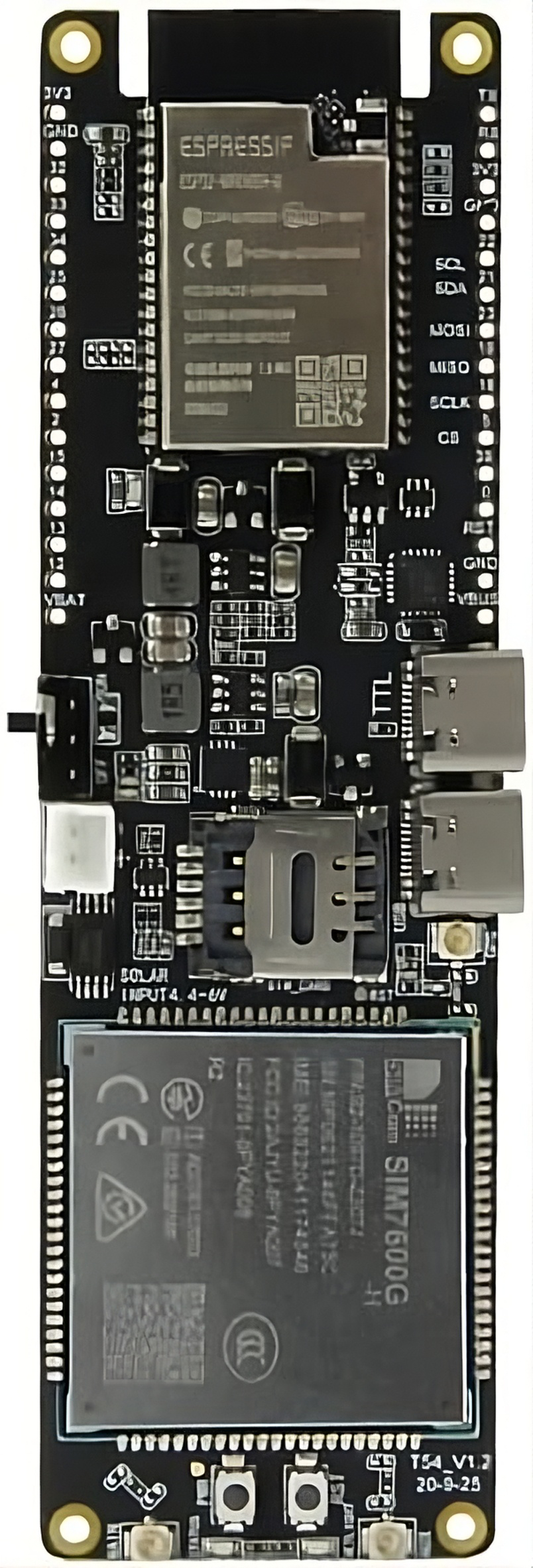
The Lilygo TTGO SIM7600G is a versatile development board designed for IoT applications. Manufactured by ESP, this board integrates the SIM7600G cellular module, which provides 4G LTE connectivity, GPS functionality, and support for various communication protocols. It is an ideal solution for projects requiring reliable wireless communication, location tracking, and integration with sensors or peripherals.
Explore Projects Built with Lilygo TTGO SIM7600G


Explore Projects Built with Lilygo TTGO SIM7600G
Common Applications and Use Cases
- IoT devices requiring 4G LTE connectivity
- GPS-based tracking systems
- Remote monitoring and control systems
- Smart agriculture and environmental monitoring
- Industrial automation and telemetry
- Prototyping cellular-enabled projects
Technical Specifications
Key Technical Details
| Parameter | Specification |
|---|---|
| Manufacturer | ESP |
| Part ID | 32 |
| Cellular Module | SIM7600G |
| Connectivity | 4G LTE, GPS, GSM, GPRS, EDGE |
| Microcontroller | Integrated with the SIM7600G module |
| Input Voltage | 5V (via USB-C) |
| Power Consumption | ~1.5W (varies based on usage) |
| Interfaces | UART, GPIO, I2C, SPI |
| Antenna Ports | LTE and GPS antenna connectors |
| Dimensions | 85mm x 30mm |
| Operating Temperature | -40°C to 85°C |
Pin Configuration and Descriptions
The Lilygo TTGO SIM7600G features a variety of pins for interfacing with peripherals. Below is the pinout description:
| Pin Name | Function | Description |
|---|---|---|
| 5V | Power Input | Supplies 5V power to the board |
| GND | Ground | Common ground for the circuit |
| TXD | UART Transmit | Transmits serial data |
| RXD | UART Receive | Receives serial data |
| GPIO | General Purpose I/O | Configurable digital input/output pins |
| I2C_SCL | I2C Clock Line | Clock signal for I2C communication |
| I2C_SDA | I2C Data Line | Data signal for I2C communication |
| SPI_MOSI | SPI Master Out Slave In | Data output for SPI communication |
| SPI_MISO | SPI Master In Slave Out | Data input for SPI communication |
| SPI_SCK | SPI Clock | Clock signal for SPI communication |
| GPS_TX | GPS UART Transmit | Transmits GPS data |
| GPS_RX | GPS UART Receive | Receives GPS data |
Usage Instructions
How to Use the Component in a Circuit
- Powering the Board: Connect the board to a 5V power source using a USB-C cable or an external power supply.
- Antenna Setup: Attach the LTE and GPS antennas to their respective connectors for optimal signal reception.
- Serial Communication: Use the TXD and RXD pins to interface with a microcontroller or computer for serial communication.
- Peripheral Connections: Connect sensors or other peripherals to the GPIO, I2C, or SPI pins as required by your application.
- Programming: The board can be programmed using the Arduino IDE or other compatible development environments.
Important Considerations and Best Practices
- Ensure proper antenna placement to avoid signal interference.
- Use a stable 5V power supply to prevent voltage fluctuations.
- Avoid exposing the board to extreme temperatures or moisture.
- When using GPS functionality, ensure the antenna has a clear view of the sky for accurate positioning.
- For cellular connectivity, insert a compatible SIM card into the SIM slot on the board.
Example Code for Arduino UNO
Below is an example of how to interface the Lilygo TTGO SIM7600G with an Arduino UNO for sending an SMS:
#include <SoftwareSerial.h>

// Define RX and TX pins for SoftwareSerial
SoftwareSerial sim7600(10, 11); // RX = pin 10, TX = pin 11

void setup() {
  // Initialize serial communication
  Serial.begin(9600); // For debugging
  sim7600.begin(9600); // For SIM7600G communication

  Serial.println("Initializing SIM7600G...");
  delay(1000);

  // Send AT command to check module status
  sim7600.println("AT");
  delay(1000);
  while (sim7600.available()) {
    Serial.write(sim7600.read()); // Print response to Serial Monitor
  }

  // Set SMS text mode
  sim7600.println("AT+CMGF=1"); // Set SMS to text mode
  delay(1000);
  while (sim7600.available()) {
    Serial.write(sim7600.read());
  }

  // Send SMS
  sim7600.println("AT+CMGS=\"+1234567890\""); // Replace with recipient's phone number
  delay(1000);
  sim7600.println("Hello from SIM7600G!"); // Message content
  delay(1000);
  sim7600.write(26); // Send Ctrl+Z to indicate end of message
  delay(5000);

  Serial.println("SMS sent!");
}

void loop() {
  // No actions in loop
}
Notes:
- Replace
+1234567890with the recipient's phone number. - Ensure the SIM card has sufficient balance and supports SMS functionality.
Troubleshooting and FAQs
Common Issues and Solutions
No Cellular Signal:
- Ensure the LTE antenna is securely connected.
- Verify that the SIM card is inserted correctly and is active.
- Check for network coverage in your area.
GPS Not Working:
- Ensure the GPS antenna is connected and has a clear view of the sky.
- Wait for a few minutes for the GPS module to acquire a signal.
Board Not Powering On:
- Verify the power source is providing 5V.
- Check the USB-C cable or external power supply for faults.
No Response to AT Commands:
- Confirm the correct baud rate is set in your code.
- Check the TXD and RXD connections between the board and the microcontroller.
FAQs
Q: Can I use this board with a 3.3V microcontroller?
A: Yes, but you will need a level shifter to safely interface the 3.3V logic with the board's 5V logic.
Q: What is the maximum data rate for LTE connectivity?
A: The SIM7600G supports LTE Cat-4 with download speeds up to 150 Mbps and upload speeds up to 50 Mbps.
Q: Does the board support voice calls?
A: Yes, the SIM7600G module supports voice calls, but additional configuration is required.
Q: Can I use this board without a SIM card?
A: The GPS functionality can be used without a SIM card, but cellular connectivity requires an active SIM card.
Q: Is the board compatible with other development platforms?
A: Yes, the board can be used with platforms like Raspberry Pi, ESP32, and STM32, in addition to Arduino.