
How to Use Header 2: Examples, Pinouts, and Specs
 Design with Header 2 in Cirkit Designer
Introduction
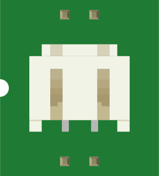
A Header 2 is a type of connector commonly used to interface with printed circuit boards (PCBs). It features two parallel rows of pins, which provide a secure and reliable connection for various electronic components and modules. These connectors are widely used in prototyping, embedded systems, and industrial applications due to their versatility and ease of use.
Explore Projects Built with Header 2
 Open Project in Cirkit Designer
 Open Project in Cirkit Designer
 Open Project in Cirkit Designer
 Open Project in Cirkit Designer
Explore Projects Built with Header 2
Open Project in Cirkit DesignerOpen Project in Cirkit DesignerOpen Project in Cirkit DesignerOpen Project in Cirkit DesignerCommon Applications and Use Cases
- Connecting microcontrollers to peripheral devices
- Interfacing PCBs in modular systems
- Prototyping and testing circuits
- Providing connections for sensors, displays, and other modules
- Industrial automation and robotics
Technical Specifications
Below are the key technical details for a standard Header 2 connector:
General Specifications
- Number of Pins: Typically ranges from 2x2 to 2x40 (custom configurations available)
- Pin Pitch: 2.54 mm (standard), with other pitches like 2.00 mm or 1.27 mm available
- Current Rating: 1A to 3A per pin (depending on the model)
- Voltage Rating: Up to 250V
- Operating Temperature: -40°C to +105°C
- Material:
- Pins: Gold-plated or tin-plated copper alloy
- Housing: Thermoplastic (UL94V-0 rated for flame resistance)
Pin Configuration and Descriptions
The pin configuration of a Header 2 connector depends on the number of pins and rows. Below is an example for a 2x4 (8-pin) Header 2 connector:
| Pin Number | Description |
|---|---|
| 1 | Signal or Power (e.g., VCC) |
| 2 | Ground (GND) |
| 3 | Signal or Data Line |
| 4 | Signal or Data Line |
| 5 | Signal or Power (e.g., VCC) |
| 6 | Ground (GND) |
| 7 | Signal or Data Line |
| 8 | Signal or Data Line |
Note: The actual pin assignments depend on the specific application and circuit design.
Usage Instructions
How to Use the Component in a Circuit
- Soldering:
- Align the Header 2 connector with the PCB holes.
- Solder each pin securely to the PCB pads, ensuring no solder bridges between adjacent pins.
- Mating:
- Connect the corresponding female header or ribbon cable to the Header 2 connector.
- Ensure proper alignment to avoid misconnection or damage.
- Wiring:
- Use appropriate wires or connectors to interface the Header 2 with other components or modules.
Important Considerations and Best Practices
- Pin Alignment: Double-check the orientation of the connector before soldering or mating.
- Current and Voltage Ratings: Ensure the connector's ratings match the requirements of your circuit.
- Mechanical Stress: Avoid excessive force when connecting or disconnecting to prevent damage to the pins.
- Environmental Conditions: Use connectors with appropriate material ratings for high-temperature or corrosive environments.
Example: Using Header 2 with an Arduino UNO
Header 2 connectors are often used to connect sensors or modules to an Arduino UNO. Below is an example of connecting a 2x4 Header 2 to an Arduino for interfacing with a sensor:
Circuit Diagram
- Pin 1 (VCC) → Arduino 5V
- Pin 2 (GND) → Arduino GND
- Pin 3 (Data) → Arduino Digital Pin 2
- Pin 4 (Data) → Arduino Digital Pin 3
Arduino Code Example
// Example code for reading data from a sensor connected via a Header 2 connector

const int sensorPin1 = 2; // Pin 3 of Header 2 connected to Digital Pin 2
const int sensorPin2 = 3; // Pin 4 of Header 2 connected to Digital Pin 3

void setup() {
  pinMode(sensorPin1, INPUT); // Set sensorPin1 as input
  pinMode(sensorPin2, INPUT); // Set sensorPin2 as input
  Serial.begin(9600);         // Initialize serial communication
}

void loop() {
  int sensorValue1 = digitalRead(sensorPin1); // Read data from sensorPin1
  int sensorValue2 = digitalRead(sensorPin2); // Read data from sensorPin2

  // Print the sensor values to the Serial Monitor
  Serial.print("Sensor 1 Value: ");
  Serial.println(sensorValue1);
  Serial.print("Sensor 2 Value: ");
  Serial.println(sensorValue2);

  delay(1000); // Wait for 1 second before reading again
}
Troubleshooting and FAQs
Common Issues Users Might Face
Loose Connections:
- Cause: Improper mating of the Header 2 connector with the female header or cable.
- Solution: Ensure the connector is fully seated and aligned correctly.
Short Circuits:
- Cause: Solder bridges between adjacent pins.
- Solution: Inspect solder joints and remove any excess solder using a desoldering tool.
Signal Interference:
- Cause: Long wires or poor grounding.
- Solution: Use shorter wires and ensure proper grounding.
Damaged Pins:
- Cause: Excessive force during connection or disconnection.
- Solution: Handle the connector gently and replace damaged pins if necessary.
FAQs
Q1: Can I use a Header 2 connector for high-current applications?
A1: Header 2 connectors are typically rated for 1A to 3A per pin. For higher currents, consider using connectors specifically designed for high-power applications.
Q2: How do I clean a Header 2 connector?
A2: Use a soft brush or compressed air to remove dust. For stubborn dirt, use isopropyl alcohol and a lint-free cloth.
Q3: Can I use a Header 2 connector in outdoor environments?
A3: Standard Header 2 connectors are not weatherproof. Use connectors with IP-rated enclosures for outdoor applications.