How to Use Display ips2.0: Examples, Pinouts, and Specs
Introduction
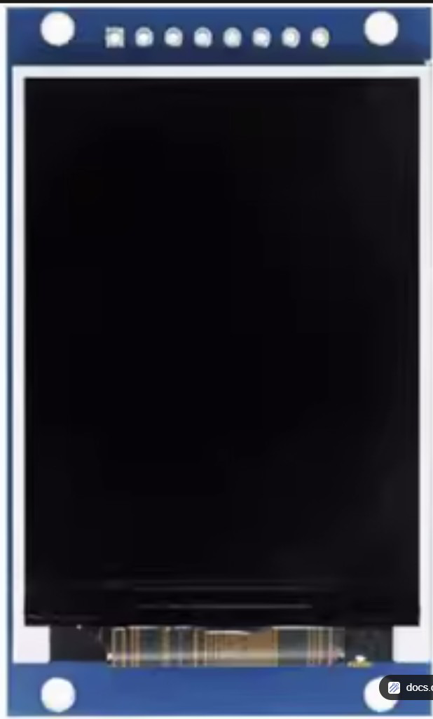
The Display IPS2.0 (Manufacturer Part ID: GMT20-02-8p) by XuanTeJia is a high-performance display interface standard designed for modern electronic devices. It supports advanced features such as high refresh rates, low latency, and superior color accuracy, making it ideal for applications requiring enhanced visual output. This component is commonly used in smartphones, tablets, gaming devices, and embedded systems where high-quality display performance is critical.
Explore Projects Built with Display ips2.0

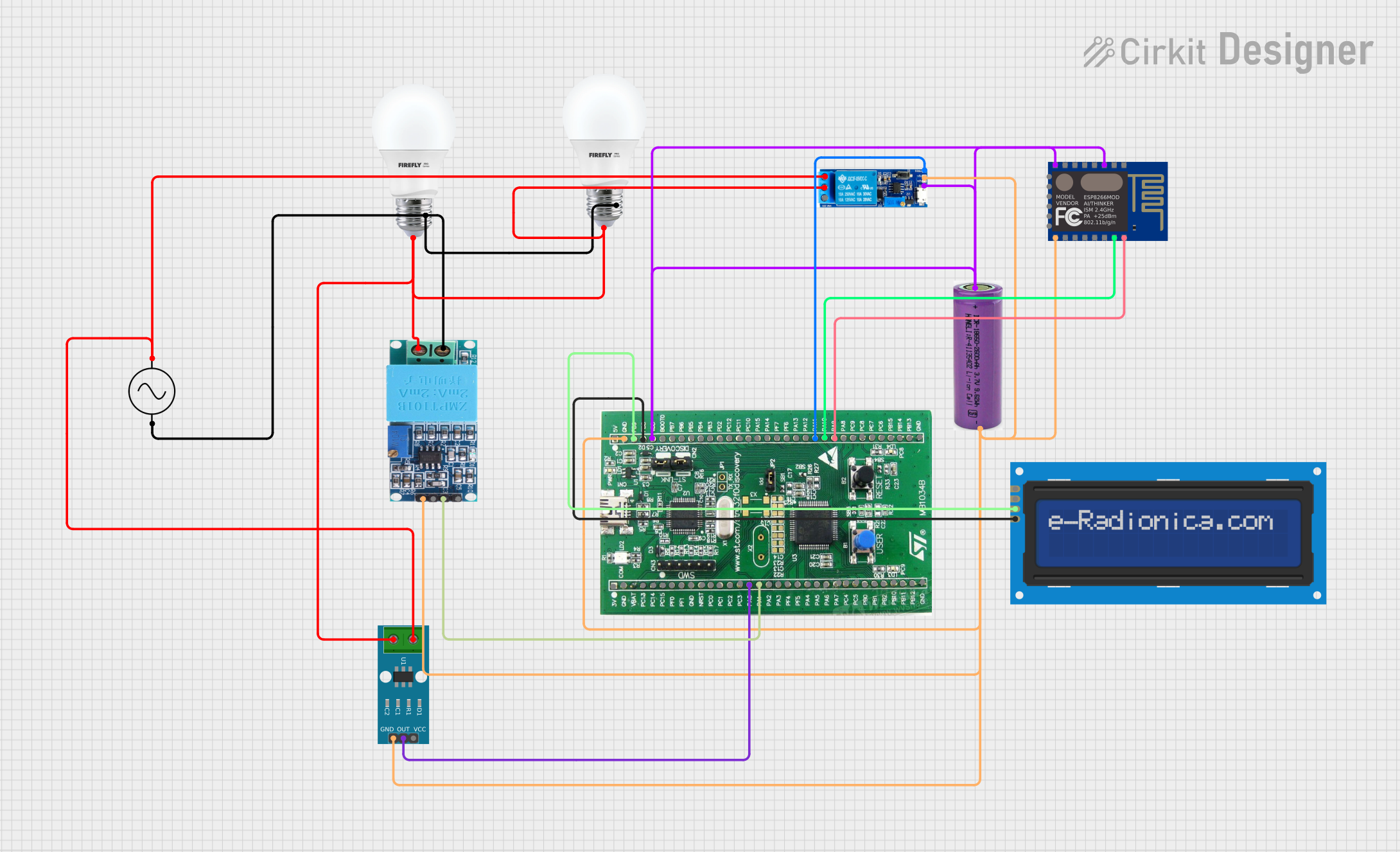
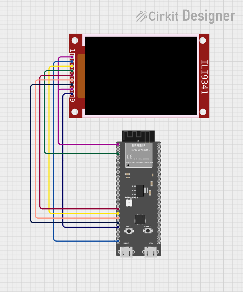

Explore Projects Built with Display ips2.0
Technical Specifications
Below are the key technical details and pin configuration for the Display IPS2.0:
Key Technical Details
| Parameter | Value |
|---|---|
| Manufacturer | XuanTeJia |
| Part ID | GMT20-02-8p |
| Display Type | IPS (In-Plane Switching) |
| Interface Standard | IPS2.0 |
| Resolution Support | Up to 1920x1080 (Full HD) |
| Refresh Rate | Up to 120 Hz |
| Latency | < 5 ms |
| Operating Voltage | 3.3V |
| Power Consumption | 1.5W (typical) |
| Operating Temperature | -20°C to 70°C |
| Storage Temperature | -40°C to 85°C |
Pin Configuration and Descriptions
The Display IPS2.0 uses an 8-pin interface for communication and power. Below is the pinout:
| Pin Number | Pin Name | Description |
|---|---|---|
| 1 | VCC | Power supply input (3.3V) |
| 2 | GND | Ground connection |
| 3 | CLK | Clock signal for synchronization |
| 4 | DATA_IN | Serial data input |
| 5 | DATA_OUT | Serial data output |
| 6 | RESET | Reset signal (active low) |
| 7 | HSYNC | Horizontal synchronization signal |
| 8 | VSYNC | Vertical synchronization signal |
Usage Instructions
How to Use the Component in a Circuit
- Power Supply: Connect the VCC pin to a stable 3.3V power source and the GND pin to the ground of your circuit.
- Data Communication: Use the CLK, DATA_IN, and DATA_OUT pins to interface with a microcontroller or processor. Ensure proper timing and synchronization.
- Synchronization Signals: Connect the HSYNC and VSYNC pins to manage horizontal and vertical synchronization for the display.
- Reset: Use the RESET pin to initialize the display. Pull the pin low momentarily to reset the component.
Important Considerations and Best Practices
- Voltage Levels: Ensure the operating voltage does not exceed 3.3V to avoid damaging the component.
- Signal Integrity: Use short and shielded wires for CLK, DATA_IN, and DATA_OUT to minimize noise and signal degradation.
- Heat Management: If the display operates for extended periods, ensure proper ventilation or heat dissipation to maintain performance.
- Initialization Sequence: Follow the recommended initialization sequence in the manufacturer's datasheet for optimal performance.
Example: Connecting to an Arduino UNO
Below is an example of how to connect and initialize the Display IPS2.0 with an Arduino UNO:
Circuit Connections
| Display IPS2.0 Pin | Arduino UNO Pin |
|---|---|
| VCC | 3.3V |
| GND | GND |
| CLK | D13 (SCK) |
| DATA_IN | D11 (MOSI) |
| DATA_OUT | D12 (MISO) |
| RESET | D8 |
| HSYNC | D9 |
| VSYNC | D10 |
Arduino Code Example
// Include necessary libraries
#include <SPI.h>

// Define pin connections
#define RESET_PIN 8
#define HSYNC_PIN 9
#define VSYNC_PIN 10

void setup() {
  // Initialize serial communication for debugging
  Serial.begin(9600);

  // Configure pins
  pinMode(RESET_PIN, OUTPUT);
  pinMode(HSYNC_PIN, OUTPUT);
  pinMode(VSYNC_PIN, OUTPUT);

  // Reset the display
  digitalWrite(RESET_PIN, LOW); // Pull RESET low to initialize
  delay(10);                    // Wait for 10ms
  digitalWrite(RESET_PIN, HIGH); // Release RESET

  // Initialize SPI communication
  SPI.begin();
  Serial.println("Display IPS2.0 initialized.");
}

void loop() {
  // Example: Send data to the display
  digitalWrite(HSYNC_PIN, HIGH); // Simulate horizontal sync
  delay(1);                      // Wait for 1ms
  digitalWrite(HSYNC_PIN, LOW);

  digitalWrite(VSYNC_PIN, HIGH); // Simulate vertical sync
  delay(1);                      // Wait for 1ms
  digitalWrite(VSYNC_PIN, LOW);

  // Add your display data handling code here
}
Troubleshooting and FAQs
Common Issues and Solutions
Display Not Turning On
- Cause: Incorrect power supply or loose connections.
- Solution: Verify that the VCC and GND pins are properly connected and the voltage is 3.3V.
Flickering or Distorted Output
- Cause: Signal noise or improper synchronization.
- Solution: Use shorter wires for CLK, DATA_IN, and DATA_OUT. Ensure HSYNC and VSYNC signals are correctly timed.
No Data Displayed
- Cause: Incorrect initialization sequence.
- Solution: Double-check the initialization code and ensure the RESET pin is toggled correctly.
Overheating
- Cause: Prolonged operation without proper ventilation.
- Solution: Add a heat sink or improve airflow around the display.
FAQs
Q: Can the Display IPS2.0 operate at 5V?
A: No, the component is designed to operate at 3.3V. Using 5V may damage the display.Q: Is the Display IPS2.0 compatible with other microcontrollers?
A: Yes, it can be used with any microcontroller that supports SPI communication and 3.3V logic levels.Q: How do I achieve the maximum refresh rate of 120 Hz?
A: Ensure your microcontroller or processor can handle the required data rate and synchronization signals.Q: Can I use this display outdoors?
A: The operating temperature range is -20°C to 70°C. Ensure the environment falls within this range for reliable operation.