How to Use LED dimmer: Examples, Pinouts, and Specs
Introduction
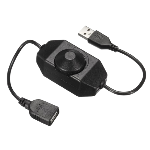
An LED dimmer is a device used to adjust the brightness of LED lights by controlling the amount of current flowing to the LEDs. It allows users to create the desired lighting ambiance, conserve energy, and extend the lifespan of LED lights. LED dimmers are commonly used in residential, commercial, and industrial lighting systems, as well as in DIY electronics projects.
Explore Projects Built with LED dimmer

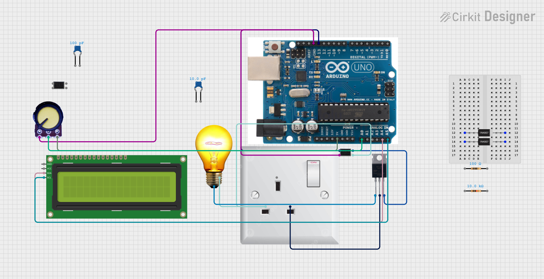
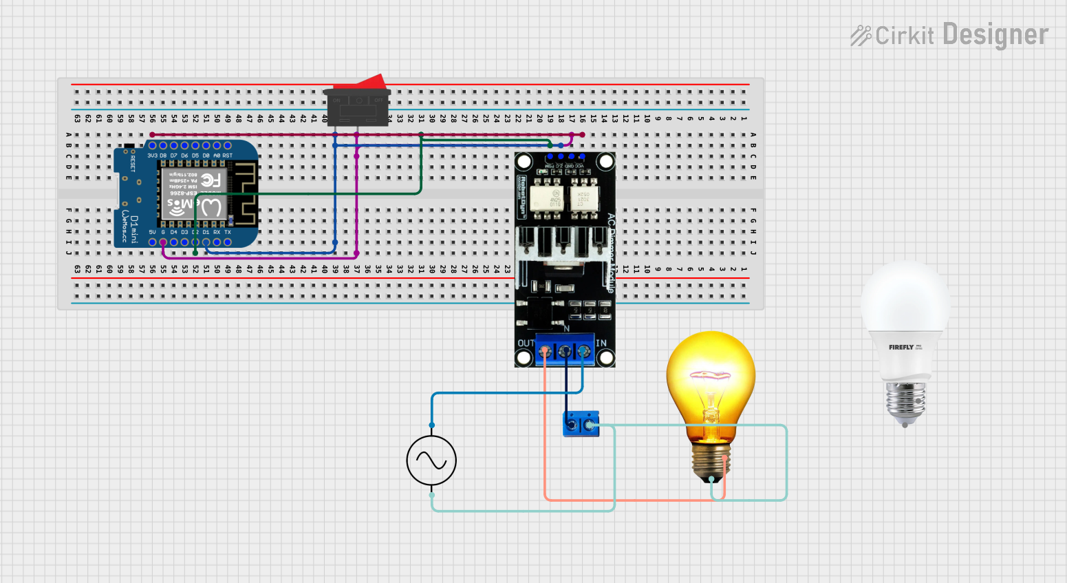
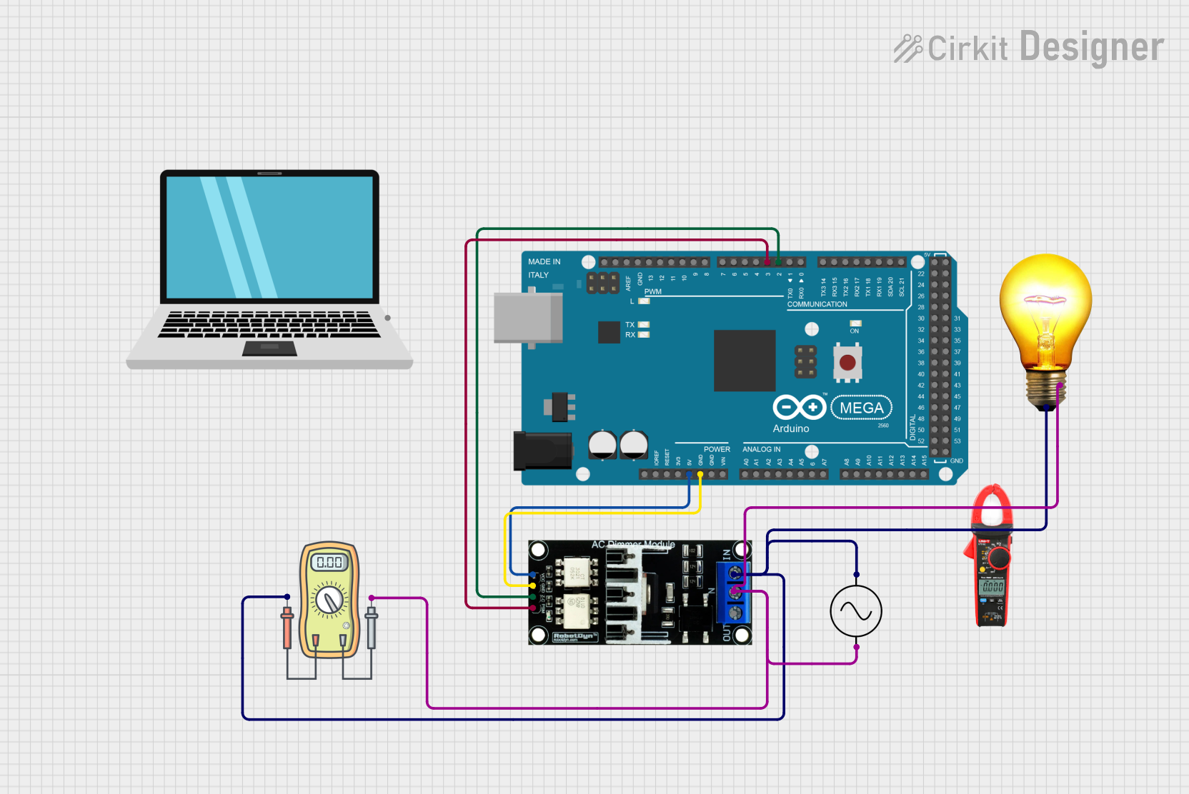
Explore Projects Built with LED dimmer
Common Applications and Use Cases
- Home lighting systems for adjustable brightness
- Stage lighting and decorative lighting
- Automotive LED lighting
- DIY electronics projects
- Energy-saving lighting solutions
Technical Specifications
Below are the general technical specifications for a typical LED dimmer. Specifications may vary depending on the specific model or manufacturer.
| Parameter | Value |
|---|---|
| Input Voltage Range | 5V to 24V DC |
| Output Current | Up to 10A (depending on model) |
| Power Rating | Up to 240W (at 24V, 10A) |
| Dimming Method | Pulse Width Modulation (PWM) |
| Dimming Range | 0% to 100% |
| Control Interface | Rotary knob, slider, or digital |
| Operating Temperature | -20°C to 60°C |
Pin Configuration and Descriptions
The pin configuration for an LED dimmer module typically includes input and output terminals. Below is a table describing the connections:
| Pin/Terminal | Description |
|---|---|
| VIN+ | Positive input voltage terminal (connect to power supply +) |
| VIN- | Negative input voltage terminal (connect to power supply -) |
| VOUT+ | Positive output voltage terminal (connect to LED +) |
| VOUT- | Negative output voltage terminal (connect to LED -) |
Usage Instructions
How to Use the LED Dimmer in a Circuit
- Connect the Power Supply:
- Connect the positive terminal of the power supply to the
VIN+pin of the dimmer. - Connect the negative terminal of the power supply to the
VIN-pin of the dimmer.
- Connect the positive terminal of the power supply to the
- Connect the LED:
- Connect the positive terminal of the LED to the
VOUT+pin of the dimmer. - Connect the negative terminal of the LED to the
VOUT-pin of the dimmer.
- Connect the positive terminal of the LED to the
- Adjust the Brightness:
- Use the rotary knob, slider, or digital control interface (depending on the dimmer model) to adjust the brightness of the LED.
Important Considerations and Best Practices
- Voltage Compatibility: Ensure the input voltage matches the operating voltage of the LED dimmer and the connected LEDs.
- Current Rating: Verify that the dimmer's current rating is sufficient for the total current draw of the connected LEDs.
- Heat Dissipation: For high-power applications, ensure proper ventilation or heat dissipation to prevent overheating.
- Polarity: Double-check the polarity of all connections to avoid damage to the dimmer or LEDs.
- PWM Frequency: If using a digital dimmer, ensure the PWM frequency is compatible with the LEDs to avoid flickering.
Example: Using an LED Dimmer with Arduino UNO
An LED dimmer can also be implemented using an Arduino UNO and a PWM pin. Below is an example code to control LED brightness using a potentiometer:
// Define the pin for the LED and the potentiometer
const int ledPin = 9;       // PWM pin connected to the LED
const int potPin = A0;      // Analog pin connected to the potentiometer

void setup() {
  pinMode(ledPin, OUTPUT);  // Set the LED pin as an output
}

void loop() {
  int potValue = analogRead(potPin);  // Read the potentiometer value (0-1023)
  int pwmValue = map(potValue, 0, 1023, 0, 255); // Map to PWM range (0-255)
  analogWrite(ledPin, pwmValue);      // Set the LED brightness
  delay(10);                          // Small delay for stability
}
Troubleshooting and FAQs
Common Issues and Solutions
LED Does Not Light Up:
- Check all connections for proper polarity.
- Ensure the power supply is functioning and providing the correct voltage.
- Verify that the dimmer is not damaged.
LED Flickers:
- Ensure the PWM frequency is compatible with the LED.
- Check for loose or poor connections.
- Verify that the power supply is stable and not fluctuating.
Dimmer Overheats:
- Ensure the current draw of the LEDs does not exceed the dimmer's rating.
- Provide adequate ventilation or use a heatsink if necessary.
Brightness Adjustment Not Working:
- Check if the control interface (e.g., rotary knob) is functioning properly.
- Verify that the dimmer is receiving the correct input voltage.
FAQs
Q: Can I use an LED dimmer with non-LED lights?
A: No, LED dimmers are specifically designed for LEDs and may not work properly with other types of lights.
Q: Can I connect multiple LEDs to a single dimmer?
A: Yes, as long as the total current draw of the LEDs does not exceed the dimmer's current rating.
Q: What happens if I exceed the dimmer's current rating?
A: Exceeding the current rating can cause the dimmer to overheat, malfunction, or become permanently damaged.
Q: Can I use an LED dimmer with a battery-powered system?
A: Yes, as long as the battery voltage is within the dimmer's input voltage range.