How to Use Lilygo t3-s3: Examples, Pinouts, and Specs
Introduction
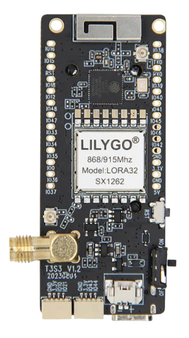
The Lilygo T3-S3 is a versatile development board built around the ESP32-S3 microcontroller. This microcontroller features dual-core Xtensa LX7 processors, integrated Wi-Fi, and Bluetooth 5.0 LE capabilities, making it ideal for Internet of Things (IoT) applications. The board is designed to support a wide range of peripherals, including GPIO, I2C, SPI, UART, and ADC, enabling developers to prototype and build embedded systems efficiently.
Explore Projects Built with Lilygo t3-s3


Explore Projects Built with Lilygo t3-s3
Common Applications and Use Cases
- IoT devices and smart home automation
- Wireless sensor networks
- Wearable technology
- Data logging and remote monitoring
- Robotics and automation
- Prototyping for AI and machine learning at the edge
Technical Specifications
The Lilygo T3-S3 is packed with features that make it a powerful tool for developers. Below are its key technical specifications:
Key Technical Details
- Microcontroller: ESP32-S3 (Xtensa LX7 dual-core, 240 MHz)
- Wireless Connectivity: Wi-Fi 802.11 b/g/n and Bluetooth 5.0 LE
- Flash Memory: 16 MB
- PSRAM: 8 MB
- Operating Voltage: 3.3V
- Input Voltage: 5V (via USB-C)
- GPIO Pins: 21 (configurable for various functions)
- Communication Interfaces: UART, SPI, I2C, I2S, CAN
- ADC Channels: 12-bit, up to 20 channels
- Power Supply: USB-C or external battery
- Dimensions: 50mm x 25mm
Pin Configuration and Descriptions
The Lilygo T3-S3 features a variety of pins for interfacing with peripherals. Below is the pinout description:
| Pin Name | Function | Description |
|---|---|---|
| GND | Ground | Common ground for the board and peripherals. |
| 3V3 | 3.3V Output | Provides 3.3V power output for external components. |
| VIN | Input Voltage | Accepts 5V input via USB-C or external power source. |
| GPIO0 | General Purpose I/O | Configurable for digital I/O, ADC, or other functions. |
| GPIO1 | General Purpose I/O | Configurable for digital I/O or UART TX. |
| GPIO2 | General Purpose I/O | Configurable for digital I/O or UART RX. |
| GPIO3 | General Purpose I/O | Configurable for digital I/O or I2C SDA. |
| GPIO4 | General Purpose I/O | Configurable for digital I/O or I2C SCL. |
| GPIO5 | General Purpose I/O | Configurable for digital I/O or SPI MOSI. |
| GPIO6 | General Purpose I/O | Configurable for digital I/O or SPI MISO. |
| GPIO7 | General Purpose I/O | Configurable for digital I/O or SPI SCK. |
| GPIO8 | General Purpose I/O | Configurable for digital I/O or PWM output. |
| GPIO9 | General Purpose I/O | Configurable for digital I/O or ADC input. |
| GPIO10 | General Purpose I/O | Configurable for digital I/O or ADC input. |
| EN | Enable | Used to enable or reset the board. |
Usage Instructions
The Lilygo T3-S3 is easy to use for prototyping and development. Follow the steps below to get started:
How to Use the Component in a Circuit
- Power the Board: Connect the board to your computer or a power source using a USB-C cable. Alternatively, you can use an external battery connected to the VIN and GND pins.
- Connect Peripherals: Use the GPIO pins to connect sensors, actuators, or other peripherals. Ensure that the voltage levels of connected devices are compatible with the 3.3V logic of the board.
- Program the Board: Use the Arduino IDE, PlatformIO, or the ESP-IDF framework to write and upload code to the board. Select "ESP32-S3" as the target device in your development environment.
- Monitor Output: Use the serial monitor in your IDE to debug and monitor the board's output.
Important Considerations and Best Practices
- Voltage Levels: Ensure that all connected peripherals operate at 3.3V logic levels to avoid damaging the board.
- Power Supply: Use a stable 5V power source for reliable operation, especially when using Wi-Fi or Bluetooth.
- Pin Multiplexing: Many GPIO pins have multiple functions. Refer to the ESP32-S3 datasheet to configure pins correctly for your application.
- Firmware Updates: Keep the ESP32-S3 firmware updated to benefit from the latest features and bug fixes.
Example Code for Arduino IDE
Below is an example of how to blink an LED connected to GPIO8 using the Arduino IDE:
// Define the GPIO pin for the LED
#define LED_PIN 8

void setup() {
  // Initialize the LED pin as an output
  pinMode(LED_PIN, OUTPUT);
}

void loop() {
  // Turn the LED on
  digitalWrite(LED_PIN, HIGH);
  delay(1000); // Wait for 1 second

  // Turn the LED off
  digitalWrite(LED_PIN, LOW);
  delay(1000); // Wait for 1 second
}
Troubleshooting and FAQs
Common Issues Users Might Face
Board Not Detected by Computer:
- Ensure the USB-C cable is a data cable, not just a charging cable.
- Check that the correct COM port is selected in your IDE.
- Install the necessary USB drivers for the ESP32-S3.
Code Upload Fails:
- Verify that the correct board and port are selected in the IDE.
- Press and hold the "BOOT" button on the board while uploading the code.
Wi-Fi or Bluetooth Not Working:
- Ensure that the board is powered by a stable 5V source.
- Check your code for correct Wi-Fi or Bluetooth configuration.
Peripherals Not Responding:
- Double-check the wiring and connections.
- Verify that the GPIO pins are configured correctly in your code.
Solutions and Tips for Troubleshooting
- Use a multimeter to check the voltage levels on the board and connected peripherals.
- Refer to the ESP32-S3 datasheet for detailed information on pin functions and electrical characteristics.
- If the board becomes unresponsive, press the "RESET" button to restart it.
By following this documentation, you can effectively use the Lilygo T3-S3 for your IoT and embedded system projects.