Cirkit Designer Logo
Cirkit Designer
Your all-in-one circuit design IDE
Home / 
Component Documentation

How to Use 16-Channel PWM Servo Driver: Examples, Pinouts, and Specs

Image of 16-Channel PWM Servo Driver
Cirkit Designer LogoDesign with 16-Channel PWM Servo Driver in Cirkit Designer

Introduction

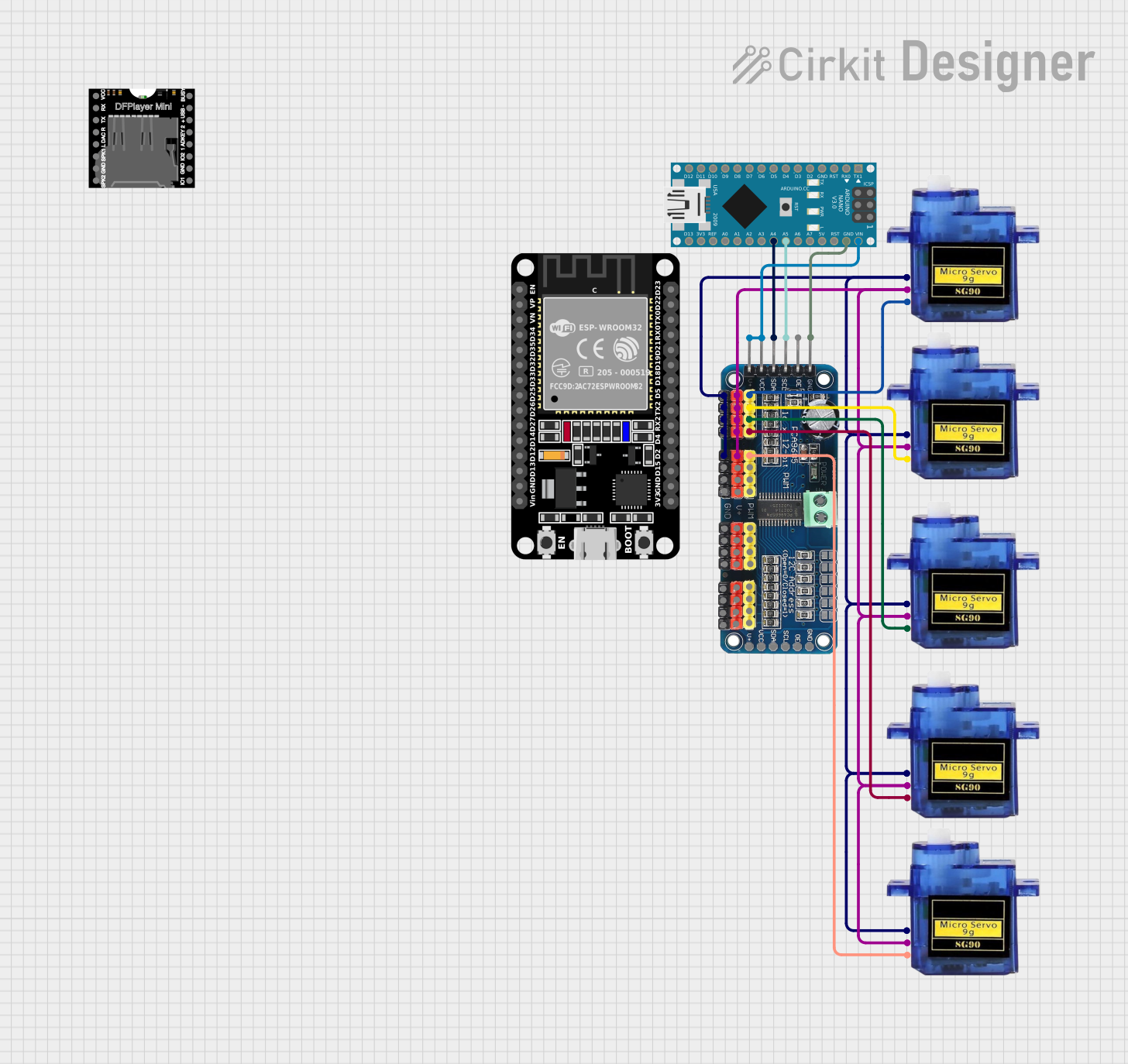
The 16-Channel PWM Servo Driver is an electronic device designed to control up to 16 servo motors simultaneously using Pulse Width Modulation (PWM). It is ideal for robotics, animatronics, custom control systems, and any application requiring precise multi-servo control. By offloading the PWM generation from the main microcontroller, such as an Arduino, it allows for smoother and more efficient operation of multiple servos.

Explore Projects Built with 16-Channel PWM Servo Driver

Use Cirkit Designer to design, explore, and prototype these projects online. Some projects support real-time simulation. Click "Open Project" to start designing instantly!
Wi-Fi Controlled 16-Channel Servo Motor System with ESP8266
Image of braile: A project utilizing 16-Channel PWM Servo Driver in a practical application
This circuit uses an ESP8266 NodeMCU microcontroller to control multiple servos via a 16-Channel PWM Servo Driver. The servos receive power from a USB power source, and the PWM signals are managed by the servo driver, which is interfaced with the microcontroller through I2C communication.
Cirkit Designer LogoOpen Project in Cirkit Designer
Arduino-Controlled Servo Driver for Multi-Channel PWM Applications
Image of SPG: A project utilizing 16-Channel PWM Servo Driver in a practical application
This circuit is designed to control multiple servo motors using an Arduino Mega 2560 microcontroller and an Adafruit 16-Channel 12-bit PWM Servo Driver. The Arduino communicates with the PWM driver over I2C (using SDA and SCL lines) to send PWM signals to individual servos for precise angle control. A separate 5V power supply provides power to the PWM driver and the servos, ensuring stable operation for high-current applications.
Cirkit Designer LogoOpen Project in Cirkit Designer
Arduino UNO Controlled Battery-Powered Servo Motor System
Image of pwm servo: A project utilizing 16-Channel PWM Servo Driver in a practical application
This circuit uses an Arduino UNO to control a 16-Channel PWM Servo Driver, which in turn drives a servo motor. The Arduino communicates with the PWM driver via I2C and is powered by a 3xAA battery pack, enabling precise control of the servo motor's position.
Cirkit Designer LogoOpen Project in Cirkit Designer
Arduino Nano and 16-Channel PWM Servo Driver Controlled Robotic Arm
Image of robotik: A project utilizing 16-Channel PWM Servo Driver in a practical application
This circuit is designed to control multiple micro servos using an Arduino Nano and a 16-Channel PWM Servo Driver. The Arduino Nano communicates with the servo driver via I2C to manage the servos, which can be used for various robotic or automation applications.
Cirkit Designer LogoOpen Project in Cirkit Designer

Explore Projects Built with 16-Channel PWM Servo Driver

Use Cirkit Designer to design, explore, and prototype these projects online. Some projects support real-time simulation. Click "Open Project" to start designing instantly!
Image of braile: A project utilizing 16-Channel PWM Servo Driver in a practical application
Wi-Fi Controlled 16-Channel Servo Motor System with ESP8266
This circuit uses an ESP8266 NodeMCU microcontroller to control multiple servos via a 16-Channel PWM Servo Driver. The servos receive power from a USB power source, and the PWM signals are managed by the servo driver, which is interfaced with the microcontroller through I2C communication.
Cirkit Designer LogoOpen Project in Cirkit Designer
Image of SPG: A project utilizing 16-Channel PWM Servo Driver in a practical application
Arduino-Controlled Servo Driver for Multi-Channel PWM Applications
This circuit is designed to control multiple servo motors using an Arduino Mega 2560 microcontroller and an Adafruit 16-Channel 12-bit PWM Servo Driver. The Arduino communicates with the PWM driver over I2C (using SDA and SCL lines) to send PWM signals to individual servos for precise angle control. A separate 5V power supply provides power to the PWM driver and the servos, ensuring stable operation for high-current applications.
Cirkit Designer LogoOpen Project in Cirkit Designer
Image of pwm servo: A project utilizing 16-Channel PWM Servo Driver in a practical application
Arduino UNO Controlled Battery-Powered Servo Motor System
This circuit uses an Arduino UNO to control a 16-Channel PWM Servo Driver, which in turn drives a servo motor. The Arduino communicates with the PWM driver via I2C and is powered by a 3xAA battery pack, enabling precise control of the servo motor's position.
Cirkit Designer LogoOpen Project in Cirkit Designer
Image of robotik: A project utilizing 16-Channel PWM Servo Driver in a practical application
Arduino Nano and 16-Channel PWM Servo Driver Controlled Robotic Arm
This circuit is designed to control multiple micro servos using an Arduino Nano and a 16-Channel PWM Servo Driver. The Arduino Nano communicates with the servo driver via I2C to manage the servos, which can be used for various robotic or automation applications.
Cirkit Designer LogoOpen Project in Cirkit Designer

Common Applications and Use Cases

  • Robotics arms and legs
  • Animatronic figures
  • Automated machinery
  • Multi-servo projects like hexapods
  • Remote-controlled vehicles with multiple control surfaces

Technical Specifications

Key Technical Details

  • Voltage: 5-6V (logic), 5-6V (servo power)
  • Current: 990mA max (without servos)
  • Power Ratings: 6A max (with servos, depends on the servo specifications)
  • Resolution: 12-bit, 4096 steps
  • Frequency: 40-1000Hz adjustable PWM frequency
  • Communication: I2C interface

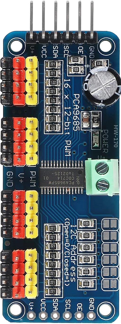
Pin Configuration and Descriptions

Pin Number Description Notes
1 GND Ground
2 VCC Logic power supply (5-6V)
3 SDA I2C data line
4 SCL I2C clock line
5-20 Servo Channels (1-16) PWM output to servos
21 OE Output enable (active low)
22 OUTNE Output not enable (active high)
23 SERVO V+ Servo power supply (5-6V)
24 I2C ADDR Pins (A0, A1, A2, A3, A4) I2C address selection pins

Usage Instructions

How to Use the Component in a Circuit
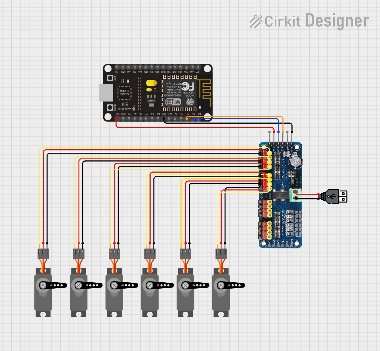
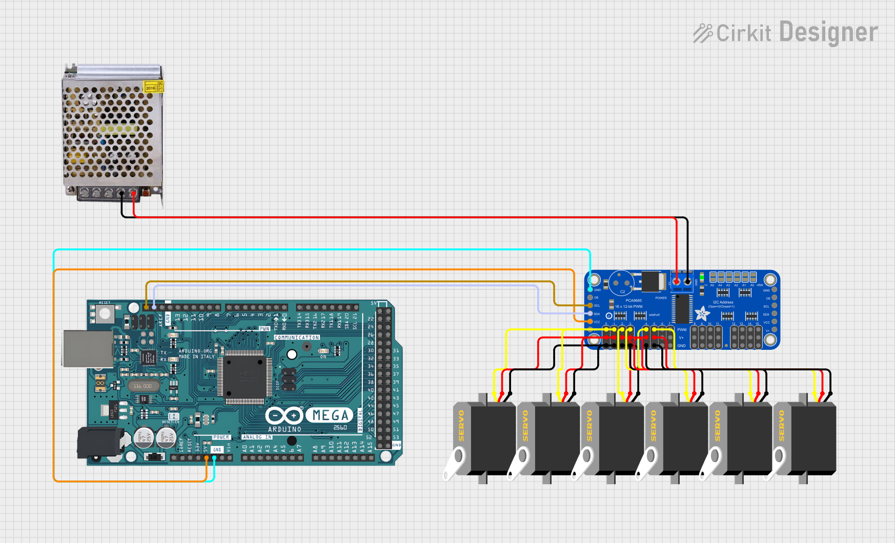
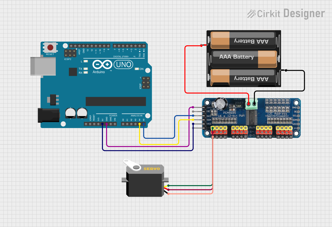
  1. Power Connections:

    • Connect the logic power supply (5-6V) to the VCC and GND pins.
    • Connect the servo power supply (5-6V) to the SERVO V+ and GND pins.
  2. I2C Connections:

    • Connect the SDA and SCL pins to the corresponding I2C data and clock lines on your microcontroller.
  3. Servo Connections:

    • Connect your servo motors to the Servo Channels (1-16) with the correct polarity.
  4. Address Selection:

    • Set the I2C address using the ADDR pins if you need to use multiple drivers on the same I2C bus.

Important Considerations and Best Practices

  • Ensure that the power supply can handle the current draw of all connected servos.
  • Use a separate power supply for the servos if the current draw is high to prevent voltage drops.
  • Always connect the grounds of the logic and servo power supplies.
  • Avoid long wires to reduce I2C communication errors.
  • Use pull-up resistors on the I2C lines if necessary.

Troubleshooting and FAQs

Common Issues Users Might Face

  • Servos not responding: Check power supplies, I2C connections, and ensure the correct I2C address is used.
  • Jittery servo movement: Ensure a stable power supply and check for signal interference.
  • Overheating: Check if the current draw exceeds the power supply capacity.

Solutions and Tips for Troubleshooting

  • Verify all connections and ensure proper polarity.
  • Use a multimeter to check for correct voltages.
  • If using an Arduino, use the Wire library to scan for the correct I2C address.
  • Reduce the PWM frequency if servos are not rated for high frequencies.

Example Code for Arduino UNO

#include <Wire.h>
#include <Adafruit_PWMServoDriver.h>

// Initialize the PWM driver
Adafruit_PWMServoDriver pwm = Adafruit_PWMServoDriver();

void setup() {
  Serial.begin(9600);
  Serial.println("16-channel PWM Servo Driver test!");

  pwm.begin();
  pwm.setPWMFreq(60);  // Set frequency to 60 Hz
}

void loop() {
  // Sweep servo on channel 0 from min to max position
  for (uint16_t pulselen = SERVOMIN; pulselen < SERVOMAX; pulselen++) {
    pwm.setPWM(0, 0, pulselen);
  }

  delay(500);
  for (uint16_t pulselen = SERVOMAX; pulselen > SERVOMIN; pulselen--) {
    pwm.setPWM(0, 0, pulselen);
  }

  delay(500);
}

Note: The Adafruit_PWMServoDriver library must be installed in the Arduino IDE. The SERVOMIN and SERVOMAX constants should be defined according to your servo's specifications.

This documentation provides a comprehensive guide to using the 16-Channel PWM Servo Driver. For further assistance, consult the manufacturer's datasheet or contact technical support.